
Method and device for protection switching

A technology for protection switching and equipment, applied in the field of communications, can solve problems such as inability to achieve results, inability to fully utilize resources, and inability to fully utilize resources.

Active Publication Date: 2013-05-22
NEW H3C TECH CO LTD
View PDF6 Cites 5 Cited by
  • Summary
  • Abstract
  • Description
  • Claims
  • Application Information

AI Technical Summary

Problems solved by technology

[0007] In practical applications, there are often more than two paths between the head node and the tail node, such as figure 1 In the MPLS TP network shown, there are actually four paths between PE1 and PE2: PE1-P1-PE2, PE1-P2-PE2, PE1-P3-PE2, and PE1-P4-PE2. However, according to the MPLS TP protection Switching mechanism, only two of the four paths can be selected for protection switching, and the other two paths cannot be used for protection switching
[0008] It can be seen that the protection switching mechanism supported by the existing MPLS TP cannot make full use of existing resources and cannot achieve a more stable effect. Similarly, other network environments that support end-to-end protection switching mechanisms also have such inadequacy. Problems with using existing resources

Method used


Image

  • Method and device for protection switching
  • Method and device for protection switching
  • Method and device for protection switching

Examples


Embodiment Construction

[0023] In order to make the objectives, technical solutions and advantages of the present invention more clearly understood, the solutions of the present invention will be further described in detail below with reference to the accompanying drawings and examples.

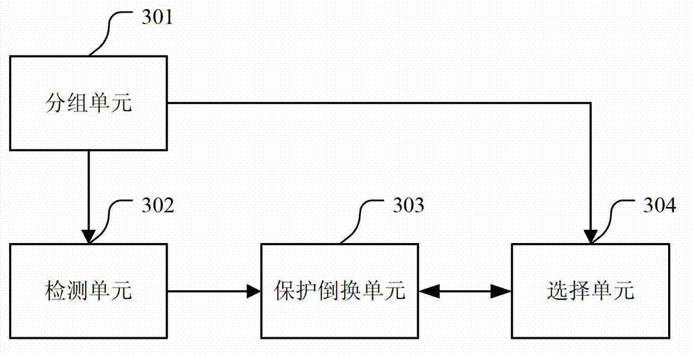
[0024] In this embodiment of the present invention, in order to make full use of the existing resources, when establishing protection switching between the head node and the tail node, a tunnel between the head node and the tail node is used as the main tunnel, and a tunnel between the head node and the tail node is used as the main tunnel. All other tunnels are added to a tunnel backup group, and the protection switching between the head node and the tail node is realized by using the primary tunnel and the tunnels in the tunnel backup group.

[0025] The protection switching method provided by the embodiment of the present invention is suitable for various networking, such as MPLS TP networking, Ethernet Virtual In...


PUM


Abstract

The invention provides a method and a device for protection switching. The method includes the steps: adding all tunnels except for a main tunnel between a head node and a tail node into a tunnel backup set when protection switching between the head node and the tail node is built; performing protection switching for service transmission between the head node and the tail node through the main tunnel and a standby tunnel selected from the tunnel backup set by the head node; and when detecting that the main tunnel fails, selecting two tunnels from the tunnel backup set, using one of the two tunnels as a secondary main tunnel, using the other tunnel as a secondary standby tunnel and performing protection switching for service transmission between the head node and the tail node through the secondary main tunnel and the secondary standby tunnel. By the method and the device, existing resources can be sufficiently used.

Description

technical field [0001] The present application relates to the field of communication technologies, and in particular, to a protection switching method and device. Background technique [0002] Multiprotocol Label Switching-Transport Architecture (MPLS Transport Profile, MPLS TP) is a connection-oriented multi-service transport technology based on packet switching, which can not only carry carrier-class Ethernet services well, but also take into account traditional TDM and ATM services. , can also support IP / MPLS business transmission, and meet five basic attributes such as standardized business, high reliability, flexible scalability, strict QOS and perfect OAM. [0003] MPLS TP supports end-to-end protection switching mechanisms, including 1:1 protection switching and 1+1 protection switching. [0004] 1:1 protection switching is to provide two primary and secondary tunnels between the head node and the tail node of the tunnel. Under normal circumstances, data is transmitt...

Claims


Application Information

Patent Timeline
Patent Type & Authority Applications(China)
IPC IPC(8): H04L12/703H04L12/723H04L45/28H04L45/50
Inventor 郑刚廖以顺
Owner NEW H3C TECH CO LTD
Learn More