
In-situ stress-temperature loading device for neutron diffraction technology

A loading device and in-situ stress technology, applied in the direction of applying stable tension/pressure to test the strength of materials, can solve the problems of large volume, heavy quality, and difficult promotion

Inactive Publication Date: 2013-05-22
INST OF NUCLEAR PHYSICS & CHEM CHINA ACADEMY OF
View PDF7 Cites 33 Cited by
  • Summary
  • Abstract
  • Description
  • Claims
  • Application Information

AI Technical Summary

Problems solved by technology

[0004] In order to overcome the shortcomings of the existing neutron diffraction technology spectrometer equipped with environmental loading equipment, large volume, heavy mass, and difficulty in popularization, the present invention provides an in-situ stress-temperature loading device for neutron diffraction technology, which can be used in many A small stress-temperature loading device used on a neutron scattering (diffraction) spectrometer, realizing neutron scattering (diffraction) in-situ stress-temperature loading testing technology

Method used


Image

  • In-situ stress-temperature loading device for neutron diffraction technology
  • In-situ stress-temperature loading device for neutron diffraction technology
  • In-situ stress-temperature loading device for neutron diffraction technology

Examples


Embodiment 1

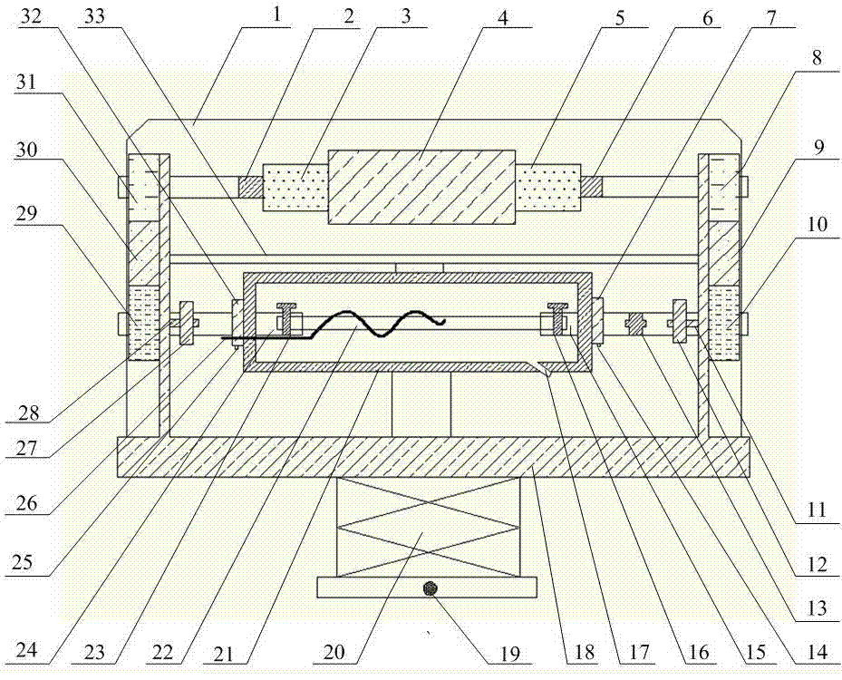
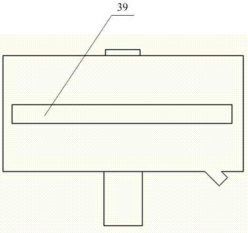
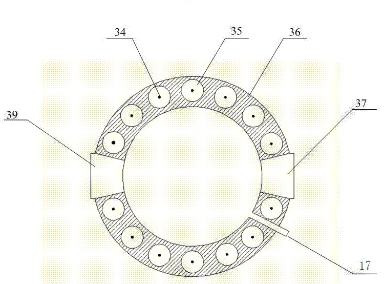
[0020] figure 1 It is a structural schematic diagram of the in-situ stress-temperature loading device for neutron diffraction technology of the present invention, Figure 2a It is a sectional view of the high-temperature furnace body 21 in the present invention, Figure 2b It is the front view of the high-temperature furnace body in the present invention, Figure 2c It is the back view of the high temperature furnace body in the present invention. exist figure 1~ In Fig. 2, the in-situ stress-temperature loading device for neutron diffraction technology of the present invention includes a drive assembly, a power transmission and conversion assembly, a guide assembly, a signal detection assembly, a high temperature furnace assembly, a frame and a control software part; The drive assembly includes a hollow shaft servo motor 4, a second reducer 3 and a first reducer 5; the power transmission and conversion assembly includes a second coupling 2, a first coupling 6, and a first ...

Embodiment 2

[0029] The basic structure of this embodiment is the same as that of Embodiment 1, except that the neutron source used in the neutron diffraction technique is a pulsed reactor neutron source.

Embodiment 3

[0031] The basic structure of this embodiment is the same as that of Embodiment 1, except that the neutron source used in the neutron diffraction technique is a spallation neutron source.


PUM


Abstract

The invention discloses an in-situ stress-temperature loading device for a neutron diffraction technology. A frame in the device is designed into a door frame type structure, a hollow-shaft servomotor is utilized for driving multiple stages of gears with the same specification and the size to rotate via a speed reducer, and the horizontal motion operation of a test sample can be further realized through a guide component and a clamp. By controlling the forward rotation (reverse rotation) of the hollow-shaft servomotor, bidirectional synchronous drawing (compression) of the test sample is realized; and by controlling the rotational speed of the hollow-shaft servomotor, the speed regulation of drawing (compression) of the test sample is realized. A cavity type high-temperature furnace with the design based on a resistance heat radiation structure is matched with the frame to use, a temperature control instrument is used for controlling the temperature in a body cavity of the high-temperature furnace, fan-shaped through holes are respectively formed in the neutron incidence direction and the scattering direction, and quartz glass is further used for sealing. The in-situ stress-temperature loading device for the neutron diffraction technology, disclosed by the invention, can be used on a variety of neutron scattering (diffraction) spectrometers for realizing the neutron scattering (diffraction) in-situ stress-temperature loading testing technology.

Description

technical field [0001] The invention belongs to the technical field of in-situ measurement of material structure and performance in the environment of neutron diffraction combined with stress-temperature loading, and specifically relates to an in-situ stress-temperature loading device for neutron diffraction technology, which is suitable for various pulleys It is a device for measuring the structure and mechanical properties of materials under different stretching (compression) motion modes, different stretching rates and different temperature conditions. Background technique [0002] The neutron diffraction analysis technique is similar to the X-ray analysis method, which calculates the strain according to the displacement of the diffraction peak, and then converts it into a stress result. Compared with the latter, neutrons have obvious advantages in penetration depth and distinguishing adjacent elements. It is generally believed in the industry that neutron diffraction ana...

Claims


Application Information

Patent Timeline
IPC IPC(8): G01N3/18
Inventor 张莹孙光爱席治国庞蓓蓓李建陈波崔元萍刘耀光汪小琳
Owner INST OF NUCLEAR PHYSICS & CHEM CHINA ACADEMY OF
Learn More