
Externally arranged steam cooler system in heat regenerative system of power plant and heat regenerative system

A technology of steam cooler and heat recovery system, which is applied in the directions of steam generation, feed water heater, preheating, etc. It can solve the problems that the existing technology has not been widely promoted, has high requirements for operation safety, and affects the return on investment, etc., and achieves The effect of increasing the return on investment, improving the safety of operation, and reducing the cost

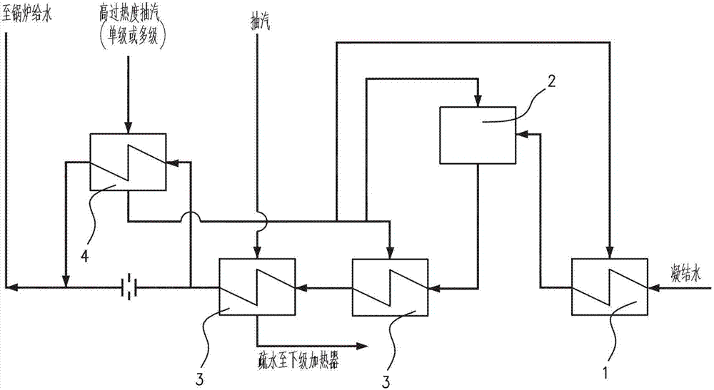
Active Publication Date: 2013-05-22
CHINA POWER ENG CONSULTING GRP CORP EAST CHINA ELECTRIC POWER DESIGN INST
View PDF6 Cites 6 Cited by
  • Summary
  • Abstract
  • Description
  • Claims
  • Application Information

AI Technical Summary

Problems solved by technology

High operating and design pressures lead to difficult equipment manufacturing, high cost, and high operational safety requirements. At the same time, the cost of piping systems (including pipes, fittings, valves, etc.) is high, which affects the return on investment
[0007] For many turbogenerators that have been put into operation but are not equipped with external steam coolers, although it is known that the configuration of external steam coolers can improve the efficiency of the thermal system, save energy and reduce consumption, due to the above reasons, this prior art has not been widely used. to promote

Method used


Image

  • Externally arranged steam cooler system in heat regenerative system of power plant and heat regenerative system
  • Externally arranged steam cooler system in heat regenerative system of power plant and heat regenerative system
  • Externally arranged steam cooler system in heat regenerative system of power plant and heat regenerative system

Examples


Embodiment Construction

[0023] Preferred embodiments of the present invention will be described in detail below with reference to the accompanying drawings, so as to better understand the purpose, features and advantages of the present invention. It should be understood that the embodiments shown in the drawings are not intended to limit the scope of the present invention, but only to illustrate the essence of the technical solutions of the present invention. Herein, the same or similar components are marked with the same reference numerals.

[0024] In the present invention, the term "external steam cooler" refers to the heat exchange surface of a heater using steam with a high degree of superheat, which can be divided into a superheated steam cooling section, a saturated steam condensation section and a hydrophobic cooling section. The conventional superheated steam cooling section It can be integrated with other heat exchange sections into the same heater, or part of the superheated steam cooling ...


PUM


Abstract

The invention provides an externally arranged steam cooler system in a heat regenerative system of a power plant and the heat regenerative system. The heat regenerative system comprises multiple stages of water feeding heaters, a deaerating heater, a water feeding pipeline and a water drainage pipeline. The externally arranged steam cooler system comprises an externally arranged steam cooler and a steam pipeline, wherein the externally arranged steam cooler is arranged on the water drainage pipeline of the water feeding heaters, a steam inlet of the externally arranged steam cooler is communicated with a superheat-degree steam suction port of a steam turbine through a pipeline, and the externally arranged steam cooler is used for heating water drained from the water feeding heaters. Compared with a system in which high-pressure feeding water is heated directly through an existing externally arranged steam cooler system by utilization of the superheat degree of superheat-degree steam, the externally arranged steam cooler system in the heat regenerative system of the power plant can improve efficiency of a thermal system, can remarkably lower the fabricating cost of equipment and the pipelines, can improve the rate of return on investment and can expand the application scope of the energy-saving and consumption-lowering technology at the same time.

Description

technical field [0001] The invention relates to thermal power generation equipment, in particular to an external steam cooler system in the heat recovery system of thermal power generation equipment. Background technique [0002] In the heat recovery system of a thermal power plant, an external steam cooler is usually equipped for the extraction steam with a high degree of superheat to improve the efficiency of the thermal system. [0003] For turbogenerators with a large amount of superheated steam, such as figure 1 Outboard steam cooler system shown for full feedwater capacity. That is, the external cooler 4 is arranged after the final feedwater heater 3, and all the feed water of the final feedwater heater 3 enters the external steam cooler 4, and the high superheat extracted steam after being cooled by the external steam cooler 4 enters A certain level of feed water heater or deaerator 2 or condensate water heater 1 before the final feed water heater 3 . [0004] For ...

Claims


Application Information

Patent Timeline
Patent Type & Authority Applications(China)
IPC IPC(8): F22D1/32
Inventor 申松林施刚夜林磊姚君
Owner CHINA POWER ENG CONSULTING GRP CORP EAST CHINA ELECTRIC POWER DESIGN INST
Learn More