Automatic rail surface derusting machine

A rust remover and rail surface technology, which is applied to tracks, track laying, track maintenance, etc., can solve the problems of incompatibility with special railway lines, ineffective signal equipment, affecting the conductivity of rails, etc., and achieve rust removal on the rail surface. The effect of automation, preventing signal equipment failure, saving working time

Inactive Publication Date: 2013-05-22
阳泉石铁车辆配件厂
View PDF5 Cites 0 Cited by
  • Summary
  • Abstract
  • Description
  • Claims
  • Application Information

AI Technical Summary

Problems solved by technology

[0002] The rails of the special railway line run in the open air, and are eroded by rain, snow, and dew all the year round. In addition, the short operating cycle causes the surface to be unclean and has rust spots, which directly affects the conductivity of the rails, resulting in the failure of the current to flow back, and the signal equipment does not work. It poses a hidden danger to the safe operation of the railway. At present, most of the methods to eliminate the above hidden dangers are manual derusting, which is labor-intensive and low-efficiency, and is especially not suitable for the normal operation of special railway lines.

Method used


Image

  • Automatic rail surface derusting machine

Examples


Embodiment 1

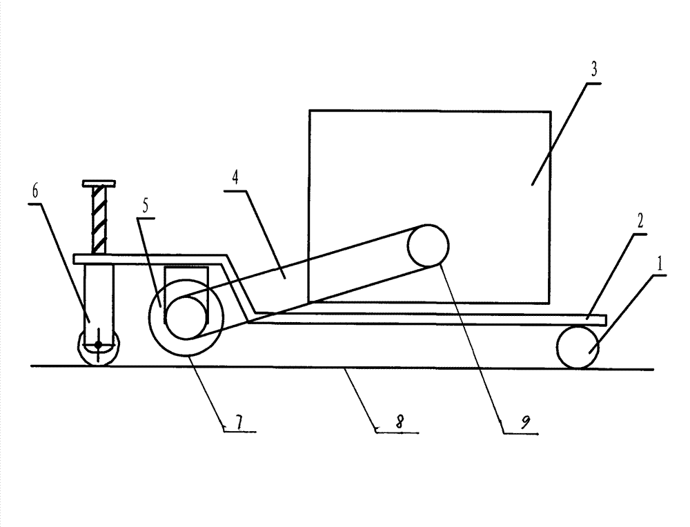
[0015] As shown in the attached figure, the automatic rail surface derusting machine adopts a fish-belly steel frame structure as a whole, which is composed of three parts: the front part, the middle part and the rear part. The front part is composed of the front guide wheel 1 and the balance wheel. The rear part is made up of rear guide wheel 7 and lifting frame 6, and the top of front guiding wheel 1 and the top surface of lifting frame 6 are arranged to connect a planar step-shaped supporting frame plate 2, on the lifting frame 6 side, the support frame plate 2 A steel wire rolling wheel 5 is fixedly arranged on the rear bottom surface, and the steel wire rolling wheel 5 is connected with the transmission wheel 9 of the power unit 3 by a belt drive 4 . Power unit 3 is arranged on the middle part, is made up of engine, belt, power transmission shaft, bearing seat, spacer and transmission wheel.

Embodiment 2

[0017] When the automatic rail surface derusting machine is on-line, the equipment is placed on one side of the steel rail 8, and the balance wheel is placed on the other side to ensure that the equipment is stable, the power source is started, and the output is smooth and stable through the transmission device. The specific speed and specific torque drive the steel wire The wheel rotates at high speed, adjust the height of the lifting frame to provide a certain pre-tightening force, so as to achieve the contact between the wire wheel and the rail surface, and derust the surface. Through experiments, the derusting effect fully meets the design requirements, restores the electrical conductivity of the rail surface, makes the current flow back, ensures the normal and reliable operation of the signal equipment, and ensures the safety of railway traffic.


PUM


Abstract

An automatic rail surface derusting machine solves the problem that rust on rail surfaces of a railway steel rail can not be removed, and is characterized in that the automatic rail surface derusting machine is integrally designed to be in a fish-belly type steel frame structure. The front portion of the fish-belly type steel frame structure is formed by a front guide wheel 1 and balanced wheels. The rear portion of the fish-belly type steel frame structure is formed by a rear guide wheel 7 and a lifting frame 6. A plane ladder-shaped support frame plate 2 is connected and fixed between the top portion of the front guide wheel 1 and the top portion of the lifting frame 6. A steel wire rolling wheel 5 is fixedly arranged on the rear bottom face of the support frame plate 2 on one side of the lifting frame and is connected with a transmission wheel 9 of a power plant 3 through a belt transmission device 4. The automatic rail surface derusting machine has the advantages of being automatic, efficient, low in labor intensity, and low in cost, and is suitable for rail surface derusting for the railway steel rail.

Description

technical field [0001] The invention belongs to the technical field of railway maintenance mechanical equipment manufacturing, and in particular relates to an automatic rail surface derusting machine, which is suitable for the application of railway rail surface derusting. Background technique [0002] The rails of the special railway line run in the open air, and are eroded by rain, snow, and dew all the year round. In addition, the short operating cycle causes the surface to be unclean and rusty, which directly affects the conductivity of the rails, resulting in the failure of the current to flow back, and the signal equipment does not work. It poses a hidden danger to the safe running of the railway. At present, the methods to eliminate the above hidden dangers mostly adopt manual rust removal, which is labor-intensive and has low efficacy, and is especially not suitable for the normal operation of special railway lines. Invention content: [0003] The purpose of the pr...

Claims


Application Information

Patent Timeline
Patent Type & Authority Applications(China)
IPC IPC(8): E01B31/02
Inventor 尹占胜张万武白守俊杨瑞刚谷国栋李世平张运生冯庆周子宏刘宝钦
Owner 阳泉石铁车辆配件厂
Why Eureka
Try Eureka