
Patient transferring bed and chassis device thereof

A transfer bed and chassis technology, used in transportation and packaging, medical transportation, vehicle rescue, etc., can solve the problem that the brake and the guide cannot be operated at the same time, and achieve the effect of solving the problem that the brake and the guide cannot be operated at the same time.

Inactive Publication Date: 2013-05-22
韩江伟
View PDF7 Cites 11 Cited by
  • Summary
  • Abstract
  • Description
  • Claims
  • Application Information

AI Technical Summary

Problems solved by technology

[0005] The purpose of the present invention is to provide a patient transfer bed to solve the problem that the existing patient transfer bed cannot be operated simultaneously by braking and guiding

Method used


Image

  • Patient transferring bed and chassis device thereof
  • Patient transferring bed and chassis device thereof
  • Patient transferring bed and chassis device thereof

Examples


Embodiment Construction

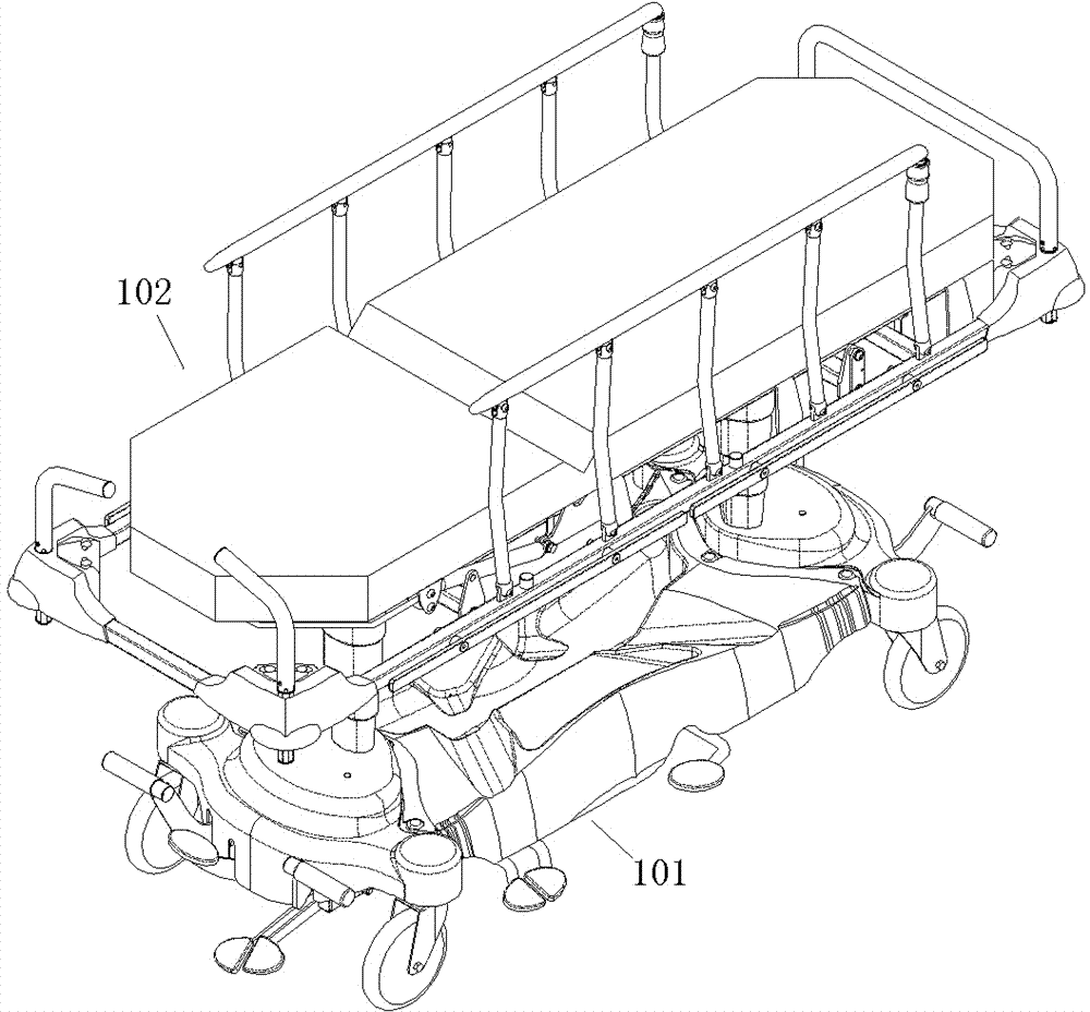
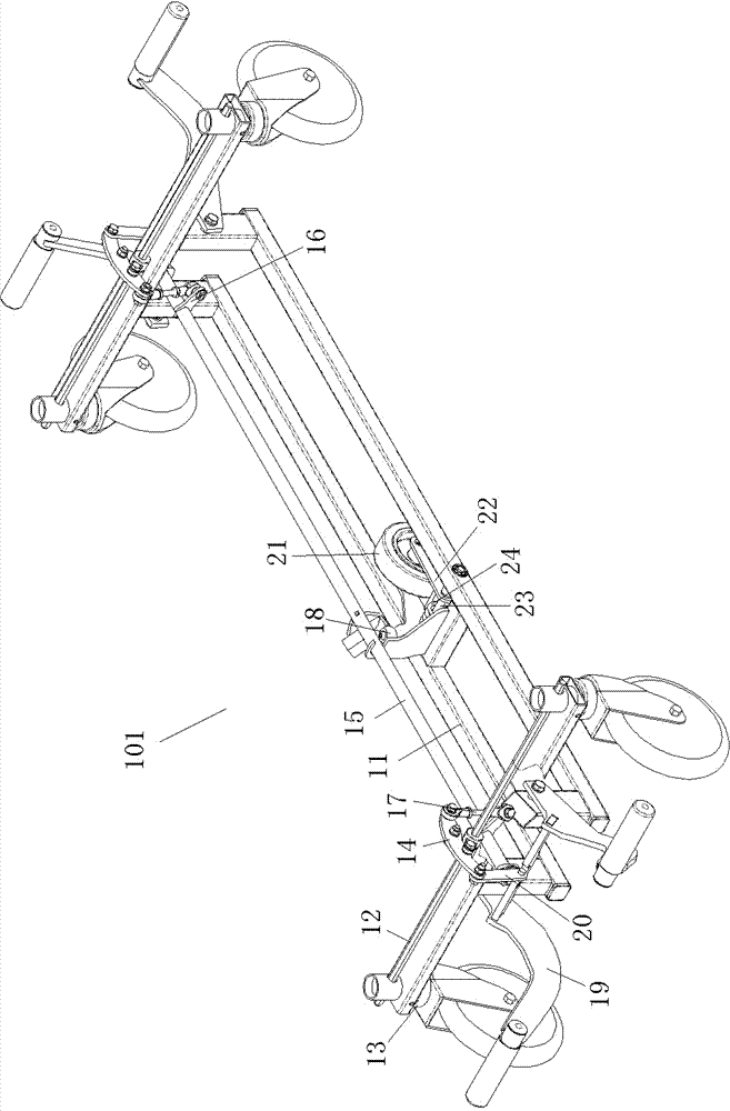
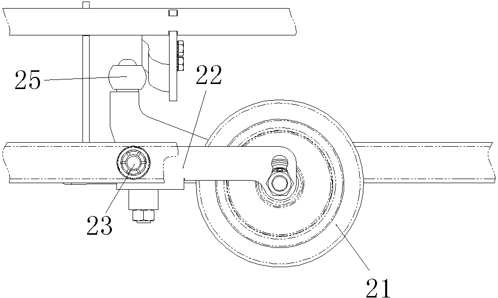
[0024] An embodiment of the patient transfer bed of the present invention, such as Figure 1-5 As shown, it includes a chassis device 101 and a bed body 102. The chassis device 101 includes a chassis 11, and a brake device is respectively provided at the front and rear ends of the chassis 11. Each brake device includes a brake lever 12 and is subject to the rotation of the brake lever 12. Controlled brake actuator 13, the structure and principle of the brake actuator 13 are the same as the brake actuator structure in the prior art, and will not be repeated here. The difference from the prior art is that the brake lever 12 of the brake device is equipped with a transmission The arm 14 and the transmission arm 14 on the two brake levers correspond to each other. In this embodiment, the transmission arm 14 is assembled on the corresponding brake lever in a non-rotating manner and forms a balance beam structure. In addition, the adjacent ends of the transmission arms corresponding ...


PUM


Abstract

The invention relates to a medical auxiliary bed, in particular to a patient transferring bed and a chassis device thereof. The transferring bed comprises a bed body, a chassis, brake devices and a guiding device. Brake devices comprise brake rods. The guiding device comprises guiding wheels and wheel frames which are used for assembling the guiding wheels. A transmission arm is fixedly assembled on each brake rod and is intersected with an corresponding brake rod, the transmission arms located on the two brake rods correspond to each other, the adjacent ends of the mutual-corresponding transmission arms are both extend inwards, a rotatable center control shaft which extends forwards and backwards is assembled on the chassis, the center control shaft enables the adjacent ends of the mutual-corresponding transmission arms to be synchronically connected together in an equidirectional and transmission mode through two connecting levers arranged at two ends of the center control shaft, at least one brake rod is connected with an operation handle which is used for driving the brake rod to rotate around an axis, and a cam mechanism which is used for being in press fit with the wheel frames and controlling the heights of the guiding wheels is arranged on the center control shaft. The patient transferring bed and the chassis device thereof solve the problem that an existing patient transferring bed cannot be simultaneously operated for braking and guiding.

Description

technical field [0001] The invention relates to a medical auxiliary bed, in particular to a patient transfer bed and its chassis device. Background technique [0002] In the prior art, four casters are provided on the chassis of the patient transfer bed, and the caster wheels are universal wheels, which are used to provide convenience for patient transfer. However, since the four casters are universal wheels, it is very easy to cause the bed to collide with the wall or the surrounding people due to factors such as inertia during the moving process, especially when turning. The casters also need to be locked to prevent them from slipping automatically. Aiming at the problem that the hospital bed will automatically slide, the Chinese patent application No. 2001201153966 discloses a caster brake device for the hospital bed. It extends in the direction and is respectively driven and connected with brake actuators at both ends. The brake actuators include eccentric devices corr...

Claims


Application Information

Patent Timeline
Patent Type & Authority Applications(China)
IPC IPC(8): A61G1/02A61G1/04
Inventor 韩江伟
Owner 韩江伟
Learn More