
Pneumatic thin film performing mechanism with built-in type anti-rotating device

A technology for actuators and pneumatic membranes, applied in valve devices, engine components, valve operation/release devices, etc., can solve the problems of diaphragm rotation damage, spring instability, linearity of regulating valves, and non-compliance of hysteresis. Achieve the effects of avoiding cracking and damage, preventing the rotation of the push rod, and ensuring stability

Active Publication Date: 2013-05-15
ZHEJIANG SUPCON FLUID TECH
View PDF6 Cites 2 Cited by
  • Summary
  • Abstract
  • Description
  • Claims
  • Application Information

AI Technical Summary

Problems solved by technology

Large-thrust pneumatic membrane actuator is a device used to provide power source for large-diameter valves (DN250-DN400). Compared with conventional pneumatic membrane actuators, the requirements for occasions are stricter and safety requirements are higher, so the structure is more However, the traditional high-thrust actuators have no built-in anti-rotation mechanism, which causes the valve core and valve stem to rotate when the pressure in the valve is high, and drives the push rod of the pneumatic diaphragm actuator to also rotate, and the push rod is driven by the push rod to rotate. The problem of the rotation damage of the diaphragm of the pneumatic diaphragm actuator caused by the rotation
If an anti-rotation key is added to the valve body assembly, the structure will be quite complicated, and the valve core and valve stem are easy to vibrate in the high-pressure differential fluctuating medium, which will seriously affect the adjustment accuracy of the valve.
Moreover, only one end of the spring in the existing large-thrust pneumatic membrane actuator is tightly fixed, and the spring is prone to instability under a large stroke, causing the linearity and hysteresis of the regulating valve to fail to meet the standard requirements, and even the spring to break

Method used


Image

  • Pneumatic thin film performing mechanism with built-in type anti-rotating device
  • Pneumatic thin film performing mechanism with built-in type anti-rotating device
  • Pneumatic thin film performing mechanism with built-in type anti-rotating device

Examples


Embodiment 1

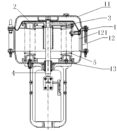
[0041] see image 3, the pneumatic membrane actuator with a built-in anti-rotation device in this embodiment is specifically a positive-acting high-thrust pneumatic membrane actuator with a built-in anti-rotation device, which includes a membrane cover assembly, a diaphragm 2, a tray 3, The elastic element and push rod 4, wherein the membrane cover assembly includes an upper membrane cover 11, a connecting pipe 12 and a lower membrane cover 13 connected in sequence, and the upper membrane cover 11, the connecting pipe 12 and the lower membrane cover 13 form the membrane cavity of the actuator, and the diaphragm 2 is fixed inside the membrane cover assembly, specifically between the upper membrane cover 11 and the connecting pipe 12, and the tray 3 is fixed on the diaphragm 2. Specifically, in this embodiment, the elastic elements are two symmetrically arranged springs 5, each The two ends of the root spring are respectively connected with the lower membrane cover 13 and the tr...

Embodiment 2

[0050] see Figure 9 , The difference between this embodiment and Embodiment 1 is that the above-mentioned built-in anti-rotation device is applied to the reaction large-thrust pneumatic film actuator, specifically, the diaphragm is fixed between the lower diaphragm cover and the connecting pipe, and the tray and the diaphragm are fixed. Connection, the tray is fixedly connected with the push rod, the anti-rotation screw on the vertical part of the built-in anti-rotation device is fixedly connected to the tray, and the bearing on the anti-rotation connecting rod on the horizontal part snaps into the anti-rotation guide groove set in the connecting pipe bottom end.

[0051] from image 3 The first embodiment shown and Figure 9 It can be seen from the second embodiment that there is a built-in anti-rotation device in the membrane cavity of the pneumatic film actuator, and the built-in anti-rotation device is fixed on the tray, and the rolling bearing at the horizontal part is...


PUM


Abstract

The invention discloses a pneumatic thin film performing mechanism with a built-in type anti-rotating device. The performing mechanism comprises a film cover component, a membrane, a tray, an elastic element and a push bar, wherein the membrane is fixed on the inner side of the film cover component, the tray is fixed on membrane, two ends of the elastic element are respectively connected with the film cover component and the tray, one end of the push bar is fixed on the tray, and the other end of the push bar penetrates through the film cover component and is exposed outside the film cover component. The pneumatic thin film performing mechanism is further provided with the built-in type anti-rotating device. The film cover component comprises an upper film cover, a connecting pipe and a lower film cover, wherein the upper film cover, the connecting pipe and the lower film cover are sequentially connected, and an anti-rotating guide component used for limiting a moving track of the built-in type anti-rotating device is arranged on the inner side of the connecting pipe. One end of the built-in type anti-rotating device is fixedly connected to the tray, and the other end of the built-in type anti-rotating device is connected with the anti-rotating guide component. The built-in type anti-rotating device can move along a track limited by the anti-rotating guide component. The built-in type anti-rotating device is arranged in the pneumatic thin film performing mechanism, not only is travel of the pneumatic thin film performing mechanism not affected, but also the push bar can be prevented from rotating.

Description

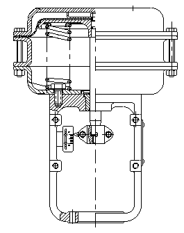
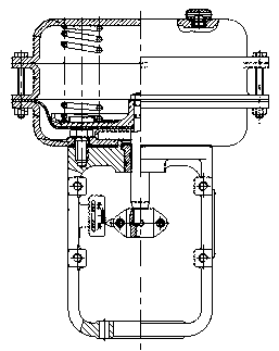
technical field [0001] The invention relates to the field of pneumatic regulating valves, in particular to a pneumatic film actuator with a built-in anti-rotation device. Background technique [0002] Pneumatic film actuator is an important part of pneumatic control valve. As a common driving device for pneumatic control valve, it is often used in various industries such as chemical industry and metallurgy. Pneumatic film actuators are widely used because of their simple structure, reliable action, convenient maintenance and low cost. Commonly used pneumatic film actuators are divided into two types of execution methods: positive action and reverse action, such as figure 1 and figure 2 shown. see figure 1 , when the input signal increases, the positive-acting pneumatic membrane actuator generates a thrust on the membrane diaphragm, and after the thrust overcomes the force of the spring, the push rod moves outward; see figure 2 , the input signal connection port of the...

Claims


Application Information

Patent Timeline
Patent Type & Authority Applications(China)
IPC IPC(8): F16K31/126
Inventor 王金郭玉娜张磊赵广坡高明星冯浩靓商喆威翁天毅
Owner ZHEJIANG SUPCON FLUID TECH
Learn More