Exhaust gas recirculation (EGR) cooler core body

A technology of EGR cooler and core body, which is applied to machines/engines, adding non-fuel substances to fuel, internal combustion piston engines, etc., which can solve the problem of not reaching the brazing assembly gap, unable to guarantee the brazing dimensional accuracy, EGR cooler Solve problems such as leakage at brazing joints, and achieve the effects of low production cost, easy maintenance, simple and reliable

Active Publication Date: 2015-03-25
无锡双翼汽车环保科技有限公司
View PDF10 Cites 0 Cited by
  • Summary
  • Abstract
  • Description
  • Claims
  • Application Information

AI Technical Summary

Problems solved by technology

At present, in the commonly used EGR cooler core, the connection between the threaded pipe and the fixing plate is a high-temperature resistant nickel-based brazing structure, and the assembly gap needs to be controlled within 0 ~ 0.075mm. The holes on the fixing plate are usually punched. , and its dimensional tolerance accuracy is 0.1mm. Although this process has high production efficiency, it cannot guarantee the dimensional accuracy required for brazing. Long-term use will cause leakage at the brazing part of the EGR cooler.
The commonly used connection structure between the threaded pipe and the fixed plate is: the two fixed plates adopt the same structure, several threaded pipes penetrate into the fixed plate, and then the two ends of the threaded pipe are flared to ensure that the threaded pipe will not fall off, which is convenient for future connection. The assembly of the outer cylinder and the water inlet and outlet pipes, but it is difficult to control the fit clearance within 0~0.075mm, which cannot reach the assembly clearance required for brazing

Method used


Image

  • Exhaust gas recirculation (EGR) cooler core body
  • Exhaust gas recirculation (EGR) cooler core body
  • Exhaust gas recirculation (EGR) cooler core body

Examples


Embodiment Construction

[0011] The specific embodiments of the present invention will be further described below in conjunction with the accompanying drawings.

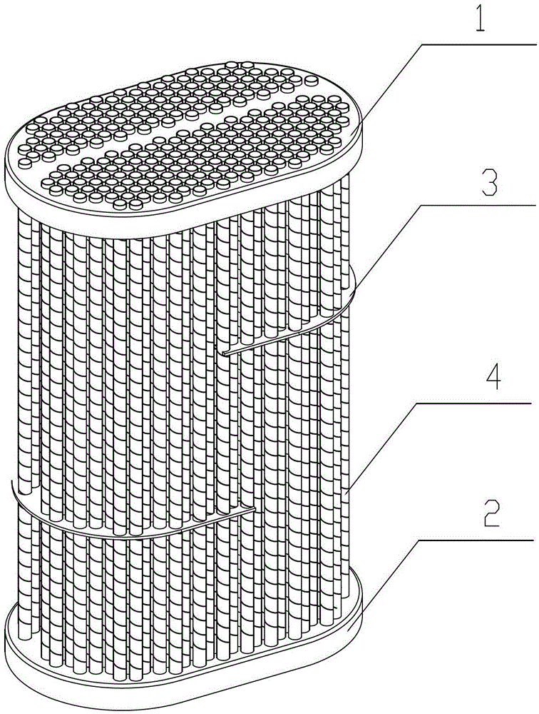
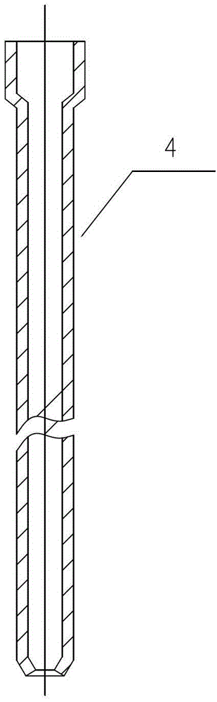
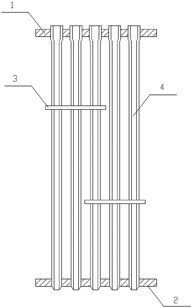
[0012] figure 1 , 2 , 3, including the upper fixed plate 1, the lower fixed plate 2, the deflector 3, the threaded pipe 4 and so on.

[0013] like figure 1 As shown, the present invention is a core body of an EGR cooler, comprising an upper fixing plate 1 and a lower fixing plate 2, the two ends of the threaded pipe 4 are respectively fixed in the through holes of the upper fixing plate 1 and the lower fixing plate 2, and the deflector 3 is fixed on the threaded pipe 4, the threaded pipe 4 is fixed on the upper fixing plate 1 and has a flared structure at one end, and one end fixed on the lower fixing plate 2 has a shrinking structure, and the diameter of the flared structure of the threaded pipe 4 is larger than that of the upper fixing plate 1 the diameter of the through hole, the diameter of the necking structure of the threaded pipe 4...


PUM


Abstract

The invention relates to the field of coolers, in particular to an exhaust gas recirculation (EGR) cooler core body and belongs to a constituent part of an EGR cooler suitable for exhaust gas recirculation in an automobile engine system. The EGR cooler core body comprises an upper fixing plate and a lower fixing plate. Two ends of a threaded tube are respectively fixed in through holes of the upper fixing plate and the lower fixing plate, a guide plate is fixed on the threaded tube, one end of the threaded tube fixed on the upper fixing plate is provided with a flaring structure, one end of the threaded tube fixed on the lower fixing plate is provided with a necking structure, the diameter of the flaring structure of the threaded tube is larger than that of the through hole of the upper fixing plate, and the diameter of the necking structure of the threaded tube is smaller than that of the through hole of the lower fixing plate. The threaded tube is installed into the upper fixing plate through external force, the other end of the threaded tube is necked, and guiding in the assembly process is facilitated. Therefore, interference fit between the flaring end of the threaded tube and the upper fixing plate and between the necking end of the threaded tube and the lower fixing plate is formed.

Description

technical field [0001] The invention relates to the field of coolers, and belongs to a component of an EGR cooler suitable for exhaust gas recirculation in an automobile engine system, specifically an EGR cooler core. Background technique [0002] EGR refers to the exhaust gas recirculation system. Its function is to take part of the exhaust gas from the engine out of the exhaust pipe, return it to the intake system of the engine after cooling, and enter the combustion chamber together with the mixed gas to reduce the combustion temperature, thereby reducing The amount of NOx generated finally meets the national emission regulations, and the EGR cooler is one of the key components of the exhaust gas recirculation system. [0003] Each EGR cooler requires many threaded pipes. At present, in the commonly used EGR cooler core, the connection between the threaded pipe and the fixing plate is a high-temperature resistant nickel-based brazing structure, and the assembly gap needs...

Claims


Application Information

Patent Timeline
Patent Type & Authority Patents(China)
IPC IPC(8): F02M25/07F02M26/29
CPCY02T10/121Y02T10/12
Inventor 张德明姚建华
Owner 无锡双翼汽车环保科技有限公司
Why Eureka
Try Eureka