
Intake structure of water intake well

A technology for water intakes and water intake wells, applied in water supply devices, drinking water devices, buildings, etc., can solve the problems of filter blockage, damage or deformation, blockage, etc., and achieve the effect of preventing loss and deformation

Active Publication Date: 2016-06-01
NAGAOKA INT
View PDF9 Cites 0 Cited by
  • Summary
  • Abstract
  • Description
  • Claims
  • Application Information

AI Technical Summary

Problems solved by technology

[0004] In the case of installing a large-diameter water intake well like this, if the water intake well is sunk into the foundation by its own weight or pressing, the water intake filter installed at the water intake may collide with the foundation during the descent of the water intake well. Frictional contact with stones, gravel, etc. in the medium will cause damage or deformation
[0005] In addition, other problems of such water intake wells are that if a filter such as a helical or linear wedge-shaped wire as shown in Patent Document 1 is used as a filter, in the long-term use process, the groundwater Gravel, garbage, sand, etc. will intrude into the slots (slots) between the wedge-shaped wires of the filter to cause clogging, which will deteriorate the water collection efficiency of the filter
In such a case, it is necessary to perform the extremely troublesome work of temporarily stopping the water intake, and the operator enters the water intake well to clean the filter to remove clogging.

Method used


Image

  • Intake structure of water intake well
  • Intake structure of water intake well
  • Intake structure of water intake well

Examples


Embodiment Construction

[0029] Embodiments of the present invention will be described below with reference to the drawings.

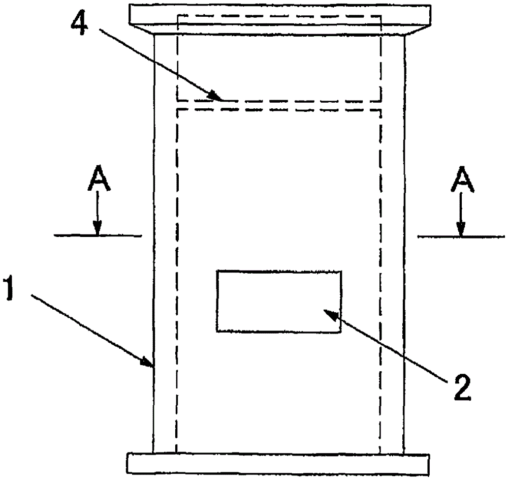
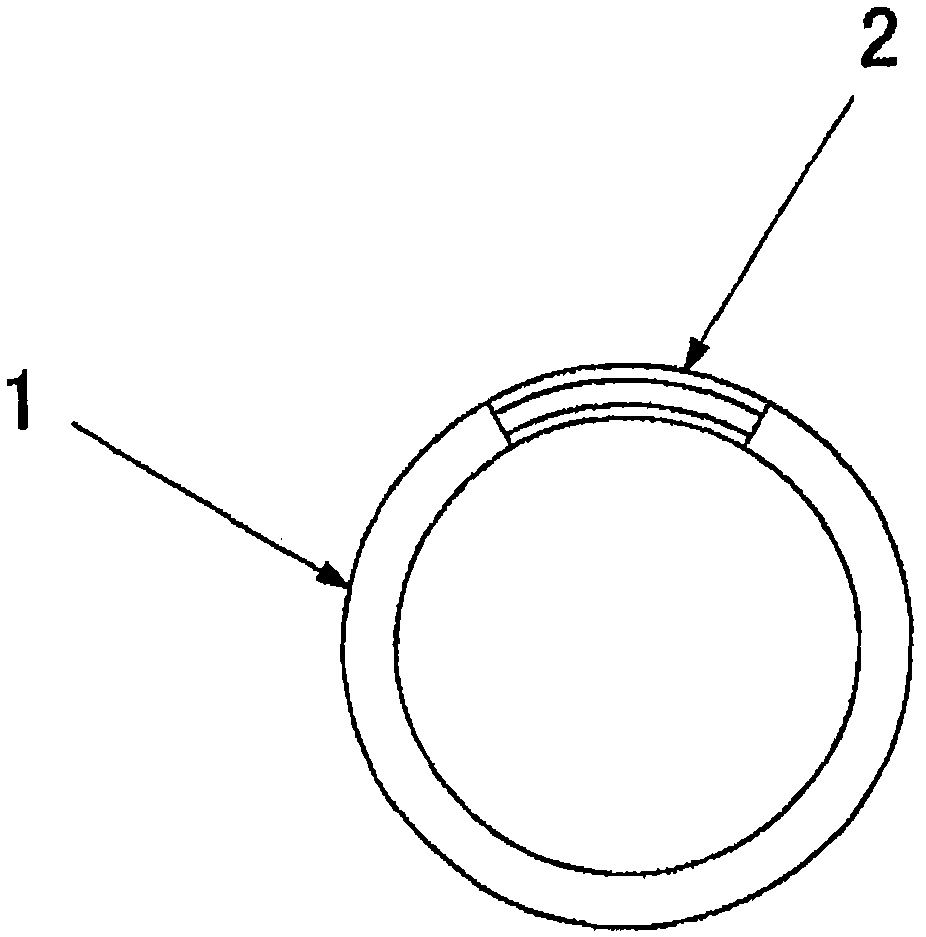
[0030] exist figure 1 and figure 2 Among them, a water intake well 1 with an elliptical cross section is formed into a cylindrical shape with an elliptical cross section by materials such as concrete or steel, and a substantially rectangular water intake 2 in a front view is provided at the lower part thereof. Mark 4 is an intermediate gangway for workers to use during construction. In this embodiment, the water intake is formed at a predetermined height on a part of the peripheral surface of the water intake well, but may be formed over the entire circumference of the water intake well. The diameter of the water intake well 1 is usually 2 m to 10 m, but it is not limited thereto.

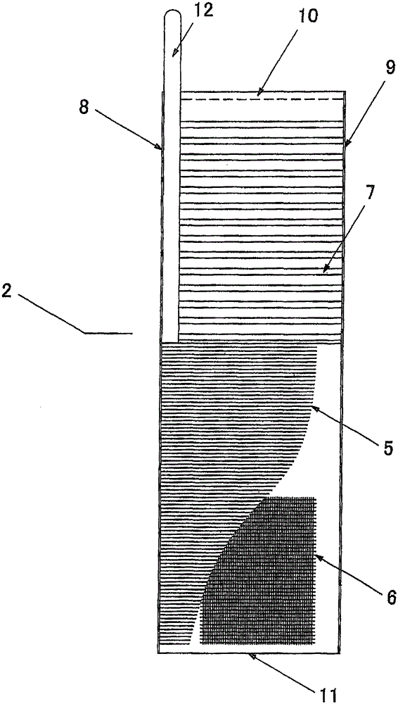
[0031] Such as image 3 As shown, viewed from the outside of the water intake well to the inside, the water intake 2 is equipped with a filter protection pipe 5, a filter 6, and a backwash pip...


PUM


Abstract

The invention provides a water intake structure for a water intake well, in disposing work of the water intake well, when the water intake well is deposited, damage and deformation caused by friction contact of a filter and stones and gravels in the foundation are prevented, and even if obstruction is generated at a seam of the filter due to long-term use of the water intake well, the obstruction can be simply removed. The water intake is disposed in a circumferential direction of the water intake well, and is provided with a specified height. The water intake is provided with: a piar of top and bottom flanges (8, 9) installed in the circumferential direction of the water intake well at upper and lower end surfaces of the water intake; a pair of end surface flanges (10, 11) installed at two end surfaces in the circumferential direction of the water intake; a filter (6) fixed on the pair of tip and bottom flanges and the pair of end surface flanges, and disposed in the whole surface range of the water intake; and a plurality of filter protection pipes (5) at the external side of a radius direction of the water intake well of the filter, wherein the plurality of filter protection pipes are arranged at a specified interval, and the two end parts are respectively fixed at the top and bottom flanges.

Description

technical field [0001] The present invention relates to a water intake structure of a water intake well, in particular to a water intake with a predetermined height provided on the entire circumference or a part of the entire circumference of a water intake well. Background technique [0002] The water intake generally has: on its upper and lower end faces, a pair of top and bottom flanges installed on the circumference of the water intake well; On the top and bottom flanges and the pair of end flanges, a water intake filter (screen) is fixed by welding or the like over the entire surface of the water intake. [0003] In the case of installing a water intake well, if the diameter of the water intake well is smaller than 2m, the foundation of the water intake ground is drilled (boring) only at the depth required for the installation of the water intake well, and the water intake well is lowered through the hole Therefore, the water intake well can be arranged in the hole, bu...

Claims


Application Information

Patent Timeline
Patent Type & Authority Patents(China)
IPC IPC(8): E03B3/08E03B3/18
Inventor 三村等
Owner NAGAOKA INT
Learn More