
Trigger control method and system of man-machine interaction operating instruction and laser emission device

An operation instruction and human-computer interaction technology, applied in the field of human-computer interaction system, can solve the problems of inconvenient use, inconvenient user-computer interaction operation, inability to realize mouse cursor movement and clicking, etc., and achieve the effect of improving operation accuracy

Active Publication Date: 2013-05-08
SHENZHEN RICHEN TECH +1
View PDF12 Cites 32 Cited by
  • Summary
  • Abstract
  • Description
  • Claims
  • Application Information

AI Technical Summary

Problems solved by technology

In the explaining scene where the computer and the projector are used together, the explainer is often far away from the computer. When the computer needs to be operated, the explainer is often required to approach the computer to perform corresponding mouse and keyboard operations. Interaction, inconvenient for users to perform human-computer interaction operations
In a further solution, a wireless presenter technology is implemented. Users can use the wireless presenter to perform simple page-turning operations, but this wireless presenter cannot perform more complex operations such as mouse cursor movement and clicking. , it is still inconvenient for users to use

Method used


Image

  • Trigger control method and system of man-machine interaction operating instruction and laser emission device
  • Trigger control method and system of man-machine interaction operating instruction and laser emission device
  • Trigger control method and system of man-machine interaction operating instruction and laser emission device

Examples


Embodiment Construction

[0035] The present invention will be further described in detail below in conjunction with the accompanying drawings and specific embodiments.

[0036] Core technical scheme of the present invention is:

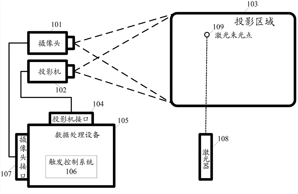
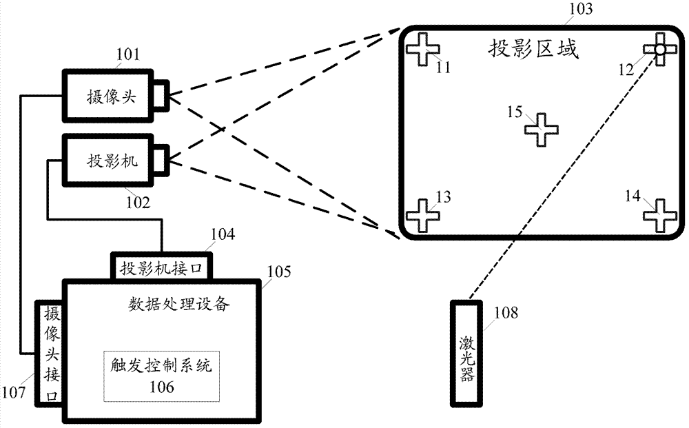
[0037] Utilize the camera device to capture the display area output by the image output device;

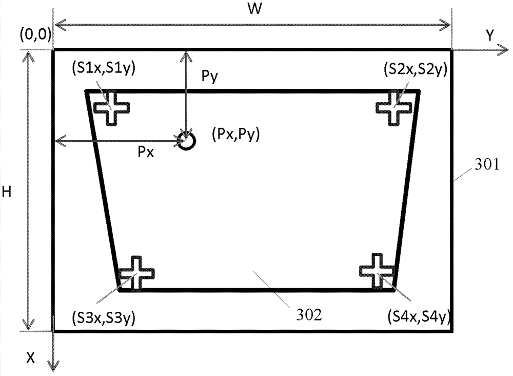
[0038] Determine the coordinate mapping transformation relationship between the display area captured by the camera device and the original picture output by the image output device. The coordinate mapping transformation relationship is represented by two parts of data: one is the coordinates of the reference calibration point in the shooting picture, and the other is the original picture and The length ratio and width ratio of the shooting picture;

[0039] Detect the laser point in the display area photographed by the camera device; determine the coordinates of the detected laser point, and convert the detected laser point according to the coordinate mapping transformation rel...


PUM


Abstract

The invention discloses a trigger control method and system of a man-machine interaction operating instruction and a laser emission device which is matched with the system to be used. A display area output by an image output device is shot by a photographic device; a coordinate mapping transformation relation between the shot display area and an original image output by the image output device is determined; a laser point is detected in the shot display area, coordinates of the laser point are determined, and the detected laser point coordinates are converted to coordinates in the original image output by the image output device according to the coordinate mapping transformation relation; and simultaneously, a coded signal of the laser point is recognized, and when a coded signal which corresponds to a certain man-machine interaction operating instruction is sent by the laser point is recognized, the man-machine interaction operating instruction corresponding to the coded signal is triggered at a position of original image coordinates which are correspondingly converted from the laser point coordinates. By means of the trigger control method and system of the man-machine interaction operating instruction and the laser emission device, a user can conveniently perform intermediate-range and long-range man-machine interaction operations.

Description

technical field [0001] The invention relates to human-computer interaction system technology, in particular to a trigger control method and system for human-computer interaction operation instructions and a matching laser emitting device. Background technique [0002] Human-computer interaction technology (Human-Computer Interaction Techniques) refers to the technology that realizes the interaction between human and data processing equipment in an effective way through the input and output devices of data processing equipment. It includes that the machine provides a large amount of relevant information and prompts to people through output or display devices, and people input relevant information and operating instructions to the machine through input devices. [0003] In the interactive process of traditional computers such as desktops and notebooks, operation instructions are triggered through input devices such as keyboards and mice. In the explanation scene where the com...

Claims


Application Information

Patent Timeline
Patent Type & Authority Applications(China)
IPC IPC(8): G06F3/042G06F3/037
CPCG06F3/00G06F3/033G06F3/0304G06F3/0325G06F3/03545G06F3/0386
Inventor 方琎
Owner SHENZHEN RICHEN TECH
Learn More