A Predictive Control Method for Complex Digital Control System

A digital control system and predictive control technology, applied in digital control, electrical program control, etc., can solve the problems of reduced prediction accuracy, low prediction accuracy, and long iterative calculation time, so as to solve the problem of sampling error, improve the search speed, The effect of reducing the time required

Inactive Publication Date: 2014-10-22
UNIV OF ELECTRONICS SCI & TECH OF CHINA
View PDF5 Cites 0 Cited by
  • Summary
  • Abstract
  • Description
  • Claims
  • Application Information

AI Technical Summary

Problems solved by technology

In order to achieve high-precision control of the controlled variable, the iterative calculation time required is relatively long, especially in some complex digital control systems with multiple dynamically changing and interrelated system parameters, the online iterative calculation time is different from other system parameters. The sum of the inherent delay time (that is, the total delay time of the system) may exceed the longest freezing coefficient time interval length allowed by the system, or exceed the total running time of the current system operating state, resulting in a decline in the prediction accuracy of the controlled quantity. Especially at the moment before and after the system operation state switching, the existing method cannot accurately determine the time point of the system operation state switching, which will inevitably bring a certain amount of overshoot
Therefore, for this type of complex digital control system, it is difficult to achieve the performance advantages of fast calculation and accurate calculation by using the first method
The second type of method does not require real-time online iterative calculations, and can obtain very fast calculation speeds, but its prediction accuracy is not high, and it is impossible to achieve high-precision control of the controlled quantity

Method used


Image

  • A Predictive Control Method for Complex Digital Control System
  • A Predictive Control Method for Complex Digital Control System
  • A Predictive Control Method for Complex Digital Control System

Examples


Embodiment Construction

[0029] The preferred embodiments of the present invention will be further described below in conjunction with the accompanying drawings.

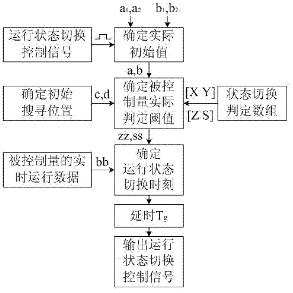
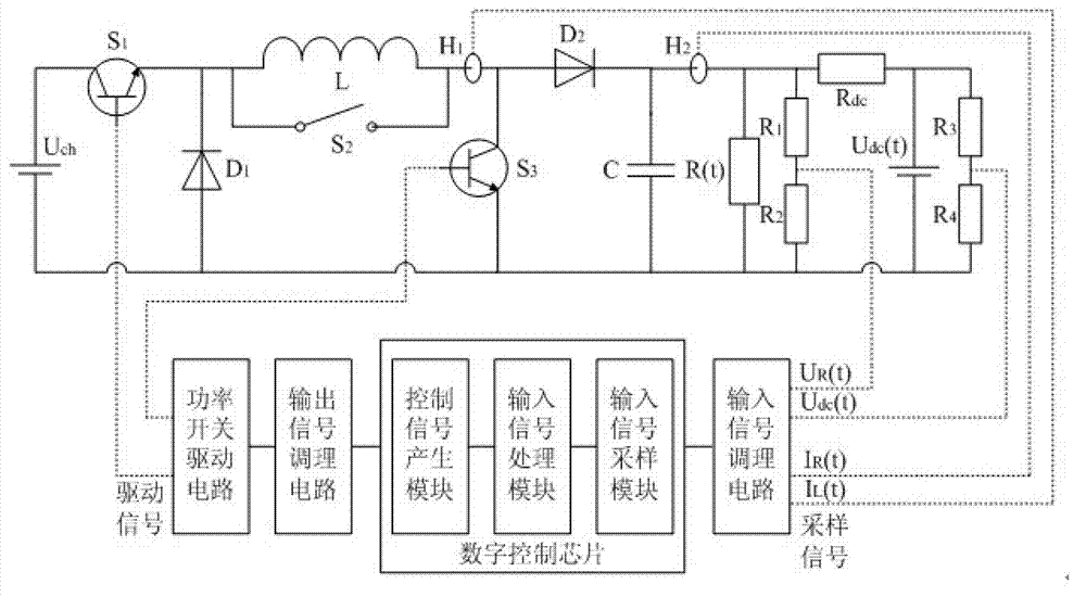
[0030] Such as figure 1 , figure 2 , image 3 , Figure 4 shown. The superconducting magnetic energy storage system solves a series of output power fluctuations including distributed power generation, power peak regulation, frequency offset, high-order harmonic suppression, voltage drop, Power system problems such as voltage surges. Since the dynamic power exchange requirements of the external DC or AC system change dynamically, it can be equivalent to a DC load resistance with constant rated voltage but dynamic change of its own resistance during the discharge process of the superconducting magnet. Take load resistance controlled constant voltage discharge control application as an example.

[0031] Superconducting magnet controlled constant voltage discharge control system (system block diagram as figure 2 Shown) consists of the ...


PUM


Abstract

The invention discloses a predictive control method for a complex digital control system. The predictive control method includes the following steps: obtaining status switching determining array of all running status in an iterative-computation mode in advance according to dynamic mathematical models and system parameters of the complex digital control system; and then combining a climbing search method and a linear interpolation method, and fast predicting parameter threshold limit value of system operating status switching and precise time points of corresponding control signals generated, and therefore controlled variables of the complex digital control system are enabled to be limited strictly within the range of preset threshold values. Compared with the prior art, the predictive control method for the complex digital control system not only maintains precision of prediction technique based on mathematical model online iterative calculation, but also has fast calculating characteristics based on an interpolation prediction method, and the predictive control method for the complex digital control system is applicable to a complex digital control system which has multiple dynamic change system parameters and is long in time of online iterative calculation.

Description

technical field [0001] The invention belongs to the technical field of digital control, in particular to a predictive control method suitable for complex digital control systems. Background technique [0002] Compared with traditional analog control, modern digital control has the advantages of strong anti-interference ability, large noise tolerance, easy implementation of complex algorithms, and repeatable programming. However, the control signal generation, transmission and execution process in various practical digital control systems inevitably have control signal delay problems, mainly including: A / D sampling conversion delay, control system calculation delay, control signal transmission Delay and execution delay of the controlled system, etc. Due to the existence of various delays, the digital control system cannot control the controlled system in time, which will affect the dynamic characteristics of the controlled system, especially the phase margin of the control l...

Claims


Application Information

Patent Timeline
Patent Type & Authority Patents(China)
IPC IPC(8): G05B19/18
Inventor 金建勋陈孝元周鑫
Owner UNIV OF ELECTRONICS SCI & TECH OF CHINA
Why Eureka
Try Eureka