Eureka AIR delivers breakthrough ideas for toughest innovation challenges, trusted by R&D personnel around the world.

Mining area surface subsidence synthetic aperture radar interferometry monitoring and calculating method

A technology of synthetic aperture radar and mining subsidence, which is applied in the directions of measuring devices, radio wave measurement systems, radio wave reflection/re-radiation, etc., and can solve the problems of needing more surface control points and being unable to correctly obtain surface subsidence

Inactive Publication Date: 2013-05-08
CHINA UNIV OF MINING & TECH
View PDF3 Cites 44 Cited by
  • Summary
  • Abstract
  • Description
  • Claims
  • Application Information

AI Technical Summary

Problems solved by technology

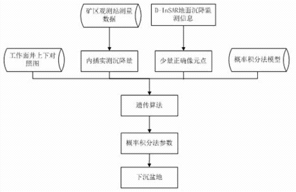
[0022] The purpose of the present invention is to provide a method for monitoring and solving synthetic aperture radar interferometry of surface mining subsidence in a mining area, so as to solve the problem that the synthetic aperture radar interferometry technology InSAR cannot correctly obtain the real surface subsidence due to loss of coherence when monitoring large surface subsidence in a mining area. At the same time, it also solves the problem that more surface control points are needed when inverting the parameters of the probability integration method in the theory of mining subsidence prediction

Method used


Image

  • Mining area surface subsidence synthetic aperture radar interferometry monitoring and calculating method
  • Mining area surface subsidence synthetic aperture radar interferometry monitoring and calculating method
  • Mining area surface subsidence synthetic aperture radar interferometry monitoring and calculating method

Examples


Embodiment 1

[0066] Embodiment 1: A monitoring and solving method for synthetic aperture radar interferometry of surface mining subsidence in a mining area, including the following steps:

[0067] 1) Generate interferogram: This step includes the selection of InSAR images, format conversion, image registration, pre-filtering, and generation of interferograms, so as to obtain the interferogram of the monitored area; the registration process is: after rough orbit registration, the image Fine registration at the element level and sub-pixel level, calculate the offset of the secondary image relative to the main image, and perform polynomial fitting, and complete the resampling of the secondary image according to the polynomial fitting coefficient; the interference process is: the main image Conjugate multiplication with the corresponding pixel of the secondary image after resampling to obtain the interference fringe pattern;

[0068] 2) Calculating the deformation phase: This step includes eli...


PUM


Abstract

A mining area surface subsidence synthetic aperture radar interferometry monitoring and calculating method belongs to mining area surface subsidence monitoring and calculating method. The method comprises the following steps: having format conversion, calibration, pre-filtering and interference to interferometric synthetic aperture radar (InSAR) data to obtain an InSAR interference phase, eliminating flat ground effect, an terrain phase and orbit errors of the interference phase by means of precise orbit data and an external dynamic effect model (DEM), obtaining phase values which only contain deformation information of a ground surface after filtering to residual phases, on the condition of large deformation gradient, through phase unwrapping, obtaining deflection of the edge of a mining subsidence basin, fusing the deflection with a few ground measured data, reversely deducing probability integral method parameters of the subsidence basin through a genetic algorithm, calculating sinking values of an arbitrary point of the whole surface subsidence basin through required probability integral method parameters and geological mining data, and therefore mining subsidence deformation field is produced. The mining area surface subsidence synthetic aperture radar interferometry monitoring and calculating method has the advantages of being high in monitoring accuracy, large in monitoring range, convenient to operate, low in cost and large in technical content.

Description

technical field [0001] The invention relates to a monitoring and solving method for surface mining subsidence in a mining area, in particular to a monitoring and solving method for synthetic aperture radar interferometric measurement of surface mining subsidence in a mining area. technical background [0002] Synthetic aperture radar interferometry technology, as an all-weather, wide-visible range, stable orbit, and high-precision geodetic technology that is unmatched by optical remote sensing, has continuously expanded its application fields and has always been a popular research subject at home and abroad. With the continuous updating of space-based radar systems and the great abundance of SAR data, this technology has achieved unprecedented development and application. Synthetic aperture radar interferometry technology is expressed in English as: InSAR, Interferometric Synthetic Aperture Radar. [0003] The "two-track difference" method in DInSAR (Differential Interferom...

Claims


Application Information

Patent Timeline
IPC IPC(8): G01S13/90
Inventor 范洪冬邓喀中薛继群陈炳乾程丹
Owner CHINA UNIV OF MINING & TECH
Why Eureka
Eureka Blog
Learn More