
Bridge loading test deflection testing instrument

A technology of load test and test instrument, which is applied in the direction of instrument, elasticity test, machine/structural component test, etc. It can solve the problems of slow test process, limitation of level accuracy, affecting test efficiency, etc., and achieves convenient level adjustment and positioning. Convenience and the effect of improving test efficiency

Inactive Publication Date: 2013-05-08
西安瑞通路桥科技有限责任公司
View PDF5 Cites 19 Cited by
  • Summary
  • Abstract
  • Description
  • Claims
  • Application Information

AI Technical Summary

Problems solved by technology

When this method is tested, it needs to be tested point by point, and multiple testers are required to complete the operation; and the test process is slow, which affects the test efficiency
In addition, due to the limitation of the accuracy of the level instrument, this method is only suitable for the deflection test of long-span bridge structures

Method used


Image

  • Bridge loading test deflection testing instrument
  • Bridge loading test deflection testing instrument
  • Bridge loading test deflection testing instrument

Examples


Embodiment Construction

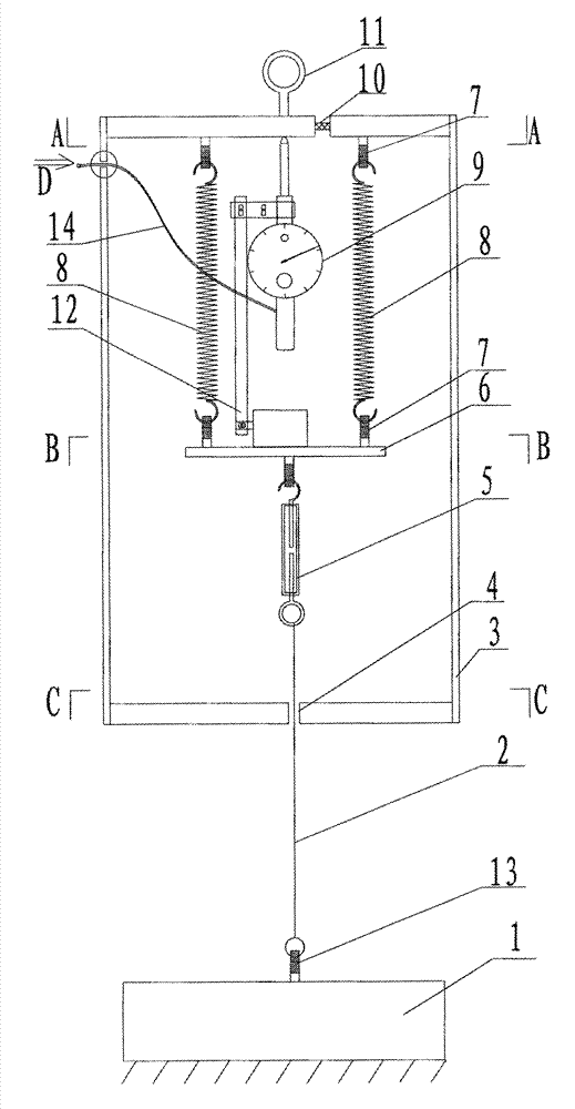
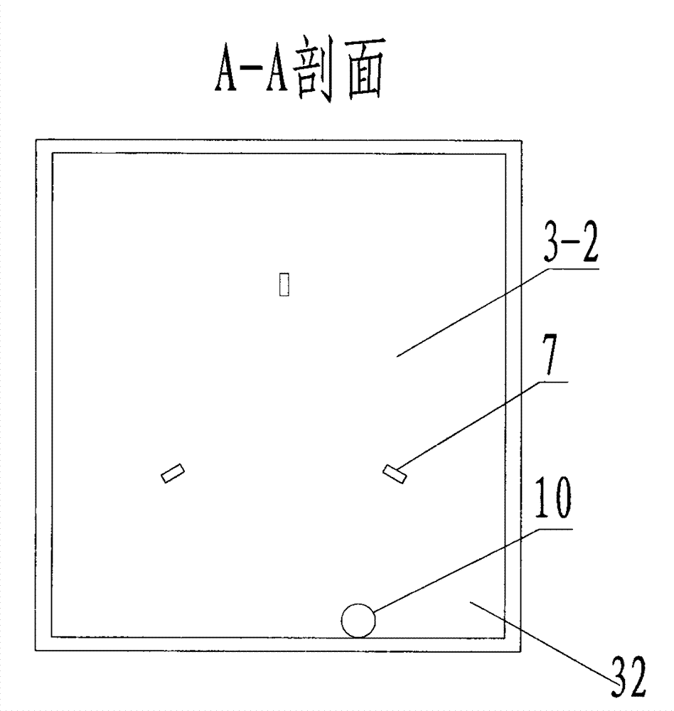
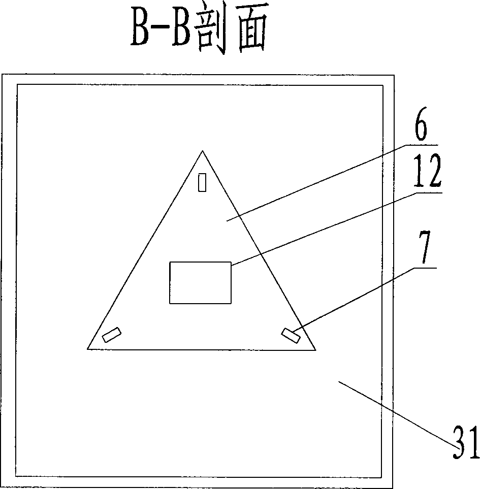
[0036] Such as Figure 1 to Figure 4 As shown, the invention includes an instrument box 3, a level 10 installed on the top surface of the box body 3 and measuring the levelness of the top surface of the box body, three springs 8 fixedly suspended on the top surface of the box body 3, connecting The test platform 6 at the lower end of the spring 8, the test instrument support 12 fixed above the test platform 6, the deflection test instrument fixed on the test instrument support 12, the turnbuckle for adjusting the elongation of the spring 8 before the deflection test 5. During the deflection test process, the deflection test rope 2 is always in a vertical state under the traction of the spring, and the counterweight 1 placed on the ground. The box body 3 has a side opening 15 .

[0037] The test platform 6, the spring 8, the test instrument support 12, the test instrument, the turnbuckle 5, and the partial deflection test rope 2 are all placed inside the box body 3.

[0038] T...


PUM


Abstract

The invention relates to the technical field of bridge deflection tests, in particular to a bridge loading test deflection testing instrument. The technical scheme is that the bridge loading test deflection testing instrument comprises an instrument tank box and a leveling instrument which is arranged on the top face of the instrument tank body and used for measuring the levelness of the top face of the instrument tank body, and side face opening holes are formed in the side faces of the tank body. Three springs are fixedly hung on the upper portion of the tank body, a testing platform is connected at the lower ends of the springs, a testing instrument support is fixedly arranged above the testing platform, and the deflection testing instrument is fixedly arranged on the testing instrument support. A turn buckle which is used for adjusting the lengths of the springs before a deflection test is hung below the testing platform. The upper end of a deflection testing rope is fixedly arranged at the lower end of the turn buckle, and the lower end of the deflection testing rope is connected with a counterweight block placed on the ground. A large hang ring is arranged on the top face of the outer portion of the tank body. The bridge loading test deflection testing instrument is reasonable in structural design, convenient to manufacture, mount and arrange, high in deflection test precision, capable of effectively solving the problems that labor and materials are consumed, working at heights is needed, mounting and dismounting are troublesome, the test precision is hard to guarantee and the like of an existing deflection test system in load tests.

Description

technical field [0001] The invention relates to the technical field of bridge deflection testing, in particular to an instrument for bridge load test deflection testing. Background technique [0002] Bridge structure deflection test is one of the important parameters for bridge superstructure detection and technical condition assessment. At present, the bridge load test is generally used to collect the change of bridge deflection under a specific load, so as to reflect the overall stiffness of the bridge structure, so as to judge the health status of the bridge in service. [0003] At present, in the bridge load test, the commonly used deflection test method is the dial indicator test method. That is to set up a bracket under the bridge structure, fix the dial indicator on the bracket, and the contact pin of the dial indicator is in contact with the bottom of the beam. The deflection test of the beam body under various working conditions is realized by the above method. W...

Claims


Application Information

Patent Timeline
Patent Type & Authority Applications(China)
IPC IPC(8): G01B5/30G01M5/00
Inventor 许宏元慕玉坤白鹏翔尹恒
Owner 西安瑞通路桥科技有限责任公司
Learn More