
Novel oil filter

An oil filter, a new type of technology, applied in the direction of machines/engines, pumping devices for elastic fluids, variable displacement pump components, etc., can solve the complex structure of the oil filter, inconvenient maintenance, difficult to clean, etc. problems, to achieve the effect of simple structure, easy cleaning and easy maintenance

Inactive Publication Date: 2013-05-08
NANTONG XINFENGXIANG HYDRAULIC CASTING
View PDF0 Cites 3 Cited by
  • Summary
  • Abstract
  • Description
  • Claims
  • Application Information

AI Technical Summary

Problems solved by technology

However, the existing oil filter is complex in structure, high in cost, inconvenient to maintain, difficult to clean, and cannot meet people's needs. Therefore, a new technical solution should be provided to solve the above problems

Method used


Image

  • Novel oil filter

Examples


Embodiment Construction

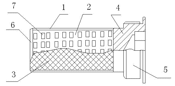
[0013] Such as figure 1 As shown, a novel oil filter of the present invention includes a casing 1 and a filter element arranged inside the casing 1. The filter element includes a frame 2 and a filter screen 3 sleeved on the frame 2. One end of the filter screen 3 is connected to a threaded 4 The joint 5 and the other end of the filter screen 3 are connected with the U-shaped sheet joint 6, and the skeleton 2 is formed by injection molding of plastic material, and several voids 7 are evenly distributed on the skeleton 2.

[0014] The present invention is a new type of oil filter, one end of filter screen 3 is connected with joint 5 with thread 4, the other end of filter screen 3 is connected with U-shaped sheet joint 6, adopting the above-mentioned structure makes the present invention not only have the function of protecting the hydraulic pump It is easy to maintain, low cost, large oil passing capacity, and easy to clean. During maintenance, the oil filter can be directly r...


PUM


Abstract

The invention discloses a novel oil filter comprising a casing and a filter core arranged in the casing. The filter core comprises a framework and a filter screen sleeved on the framework. The novel oil filter is characterized in that one end of the filter screen is connected with a threaded joint, and the other end of the filter screen is connected with a U-shaped sheet joint. The novel oil filter has the advantages of simple structure, convenience in maintenance and easiness in cleaning.

Description

technical field [0001] The invention relates to an oil filter device, in particular to a novel oil filter. Background technique [0002] The oil filter is the most commonly used device for filtering oil in construction machinery. It is usually installed at the end of the oil suction pipe of the hydraulic pump. It protects the pump, has the advantages of large oil passing capacity and small resistance, and plays an irreplaceable role. . However, the existing oil filter is complex in structure, high in cost, inconvenient to maintain, difficult to clean, and cannot meet people's needs. Therefore, a new technical solution should be provided to solve the above problems. Contents of the invention [0003] The object of the present invention is to provide a new type of oil filter with simple structure, convenient maintenance and easy cleaning in order to solve the above disadvantages. [0004] In order to achieve the above object, the technical scheme adopted in the present inv...

Claims


Application Information

Patent Timeline
Patent Type & Authority Applications(China)
IPC IPC(8): F04B53/20
Inventor 顾凤祥
Owner NANTONG XINFENGXIANG HYDRAULIC CASTING
Learn More