
A Pneumatic Clamping and Unloading Mechanism for Automatic Welding

A technology of a pneumatic clamping and unloading mechanism, applied in the field of auto parts production devices, can solve the problems of easy dislocation, easy scratches on the surface, large production output, etc., and achieves the effects of sensitive action, reduced production accidents, and simple structure.

Active Publication Date: 2015-09-23
NINGBO HONGXIECHENG AUTO PARTS CO LTD
View PDF2 Cites 0 Cited by
  • Summary
  • Abstract
  • Description
  • Claims
  • Application Information

AI Technical Summary

Problems solved by technology

[0002] Existing automobile edging products have a large production volume, the mold is inconvenient to take and place the product, and the surface is easy to scratch during the production process, but the existing mold cannot completely solve these problems. After putting into the mold, the joints of the product need to be welded, and the customer has high requirements for the size of the product. It is difficult to ensure the installation accuracy of the joints with ordinary design ideas, and misalignment is prone to occur, which will affect the appearance and quality of the product.

Method used


Image

  • A Pneumatic Clamping and Unloading Mechanism for Automatic Welding
  • A Pneumatic Clamping and Unloading Mechanism for Automatic Welding
  • A Pneumatic Clamping and Unloading Mechanism for Automatic Welding

Examples


Embodiment 1

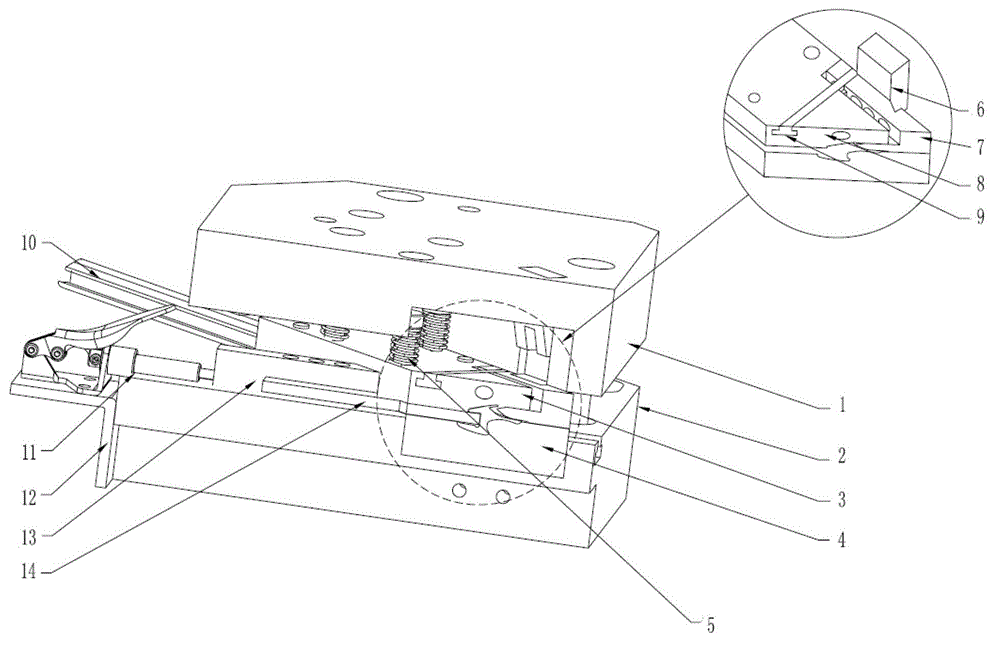
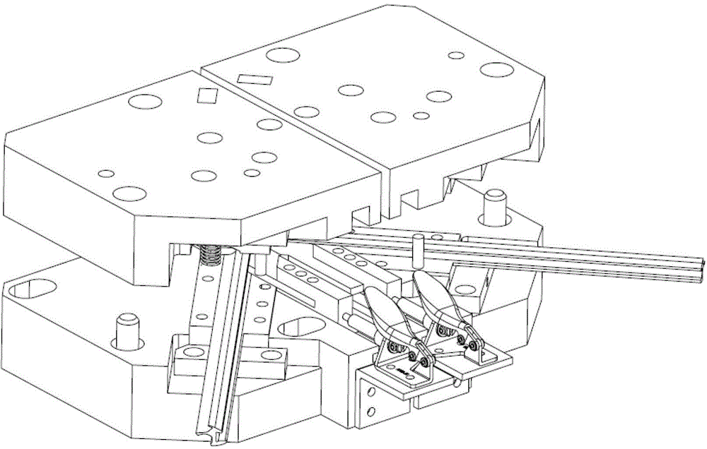
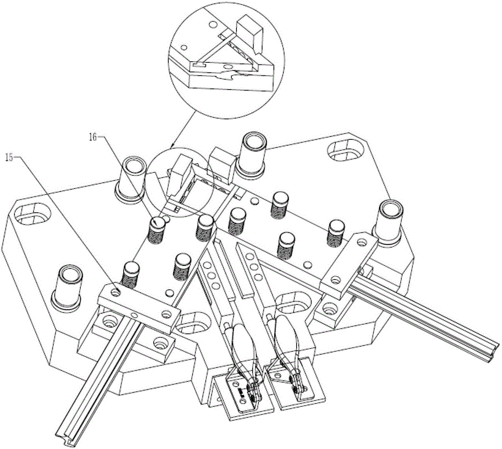
[0021] Such as Figure 1 to Figure 6 As shown, an automatic welding pneumatic clamping and unloading mechanism includes an upper template 1, a lower template 2, a first lower mold 3, a second lower mold 4, a flat wire coil spring 5, a block 6, and a clamping block 7 , pin 8, slider 9, product 10, quick chuck 11, quick chuck support block 12, product clamping block fixing plate 13, product clamping block 14, limit block 15, discharge screw 16, the Below the upper template 1 is the lower template 2. A pair of quick chuck support blocks 12 are installed and fixed in the middle of the front side of the lower template 2. Each quick chuck support block 12 is connected and fixed with a quick chuck 11. The output end of the quick chuck 11 is connected to the The product clamping block fixing plate 13 in the front is connected and fixed, the product clamping block 14 is installed in the guide groove of the product clamping block fixing plate 13, and the free end of the product clamping...


PUM


Abstract

The invention relates to an automatic welding and pneumatic clamping and discharging mechanism which comprises an upper template, a lower template, a limiting block and a screw, wherein the lower template is arranged below the upper template; the front side of the lower template is provided with a pair of quick clamp supporting blocks; quick clamps are respectively connected to the quick clamp supporting blocks; the output ends of the quick clamps are fixedly connected with a product clamping block fixing plate in the front; a product clamping block is arranged in a product clamping block fixing plate guide slot; the free end of the product clamping block is positioned in a die cavity formed by a first lower die and a second lower die; the die cavity formed by the first lower die and the second lower die is in a V shape; the outer sides of two shoulders on the top of the V-shaped tip are respectively connected with a clamping block through a slide block; and a pressing block is correspondingly arranged on the upper template above the clamping block. The cylinder action is smoothly finished through up-and-down motion of a die frame, and the mechanism is convenient and safe to mount, simple in structure and sensitive in action response; and moreover, the mechanism can be properly adjusted according to different products, and the technical problem that the welding cannot be finished due to the product with an inverted hook is solved.

Description

technical field [0001] The invention belongs to the technical field of auto parts production devices, in particular to an automatic welding pneumatic clamping and unloading mechanism. Background technique [0002] Existing automobile edging products have a large production volume, the mold is inconvenient to take and place the product, and the surface is easy to scratch during the production process, but the existing mold cannot completely solve these problems. After putting it into the mold, the joints of the product need to be welded, and the customer has high requirements for the product size. It is difficult to ensure the installation accuracy of the joints with ordinary design ideas, and misalignment is prone to occur, which will affect the appearance and quality of the product. Contents of the invention [0003] The technical problem to be solved by the present invention is to provide an automatic welding pneumatic clamping and unloading mechanism, which can ensure t...

Claims


Application Information

Patent Timeline
Patent Type & Authority Patents(China)
IPC IPC(8): B29C65/02
Inventor 刘玉权张啟金
Owner NINGBO HONGXIECHENG AUTO PARTS CO LTD
Learn More