
Shrink tunnel

A technology of shrinking channels and planes, which is applied in the direction of wrapping paper shrinkage, packaging, wrapping paper, etc., to achieve the effect of quick replacement, simple cost, and good adaptation

Active Publication Date: 2015-05-06
KRONES AG
View PDF6 Cites 0 Cited by
  • Summary
  • Abstract
  • Description
  • Claims
  • Application Information

AI Technical Summary

Problems solved by technology

If the bundle with the lower film cover pointing upwards is now transported via the constriction tunnel, this is advantageously supported by an upwardly directed hot air flow through the transport plane, but a downwardly directed hot air flow from the outflow surface stream and horizontally diverted hot air flow counteracts this desired effect

Method used


Image

  • Shrink tunnel
  • Shrink tunnel
  • Shrink tunnel

Examples


Embodiment Construction

[0037] figure 1 A schematic view of a shrinking device 1 according to the known prior art is shown. Items, in particular beverage containers, bottles 6 , cans or the like are put together in groups and wrapped with a shrink film 7 . These arrangements are also referred to as clusters 5 . The bundles 5 are transported on the conveyor belt 10 to the shrink tunnel 2 in the transport direction TR. Arranged in the shrink tunnel 2 are heating means (not shown), which, for example, impinge the bundle 5 with hot air, thereby shrinking the film 7 surrounding the bottle 6 . After the bundles 5 leave the shrink tunnel 2 , they are cooled with cooling air 22 by a fan 20 arranged above the conveyor belt 10 .

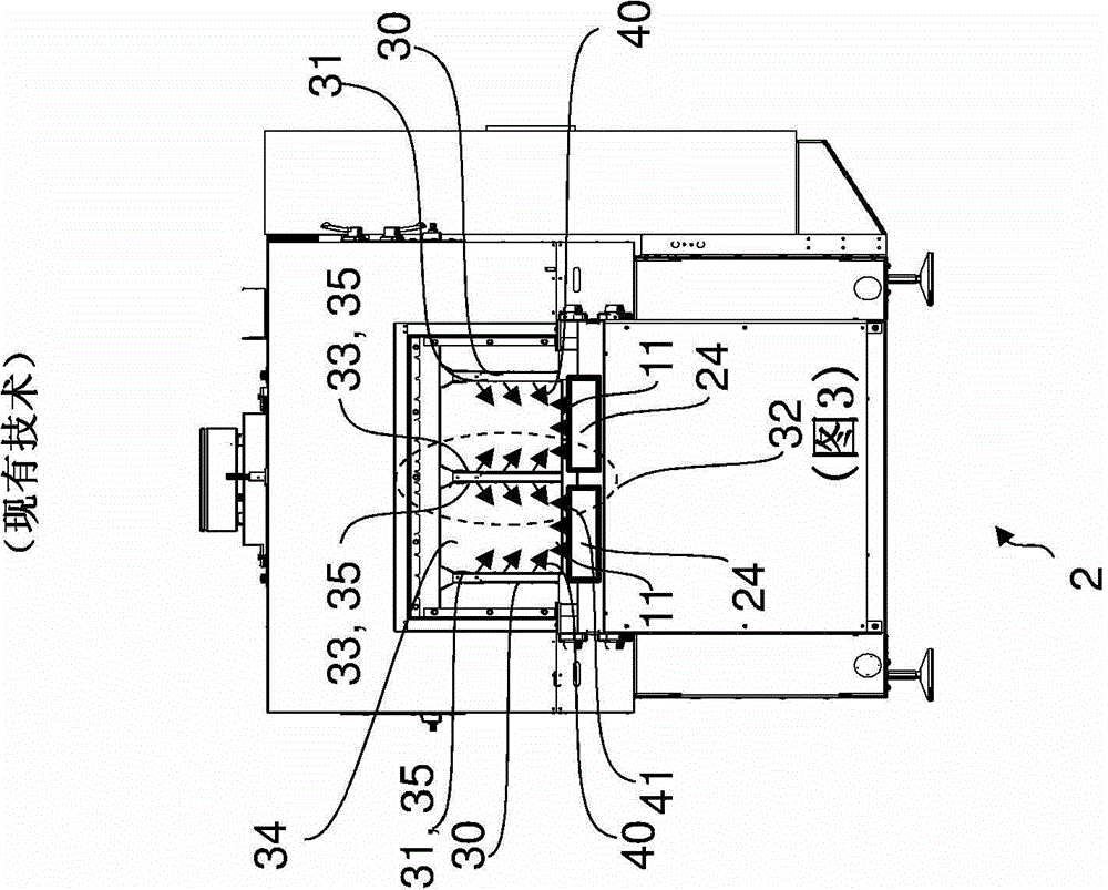
[0038] figure 2 A cross-section of the shrink tunnel 2 with two transport rails 11 for bundles (not shown) is shown. Via the so-called well walls 30 , 32 , hot air 40 is blown into the inner space 34 of the constriction channel 2 . The outer shaft wall 30 has nozzle openings 3...


PUM


Abstract

The shrink tunnel has a shaft wall (50a) that is arranged of a transport plane (TE), which is in parallel to transport direction (TR). The shaft wall is provided with a side surface (52) and upper and lower surfaces (54,55) along with the sides to form a cross-sectional area. The shrink medium (40) flowed into interior portion (34) is flowed out throught the side surface of shaft wall. The side surface and upper and lower surfaces of shaft wall are perpendicular to transport plane. The cross-sectional area of the shaft wall is tapered towards the transport plane.

Description

technical field [0001] The present invention relates to a shrink tunnel for shrinking a packaging medium around an assembly of articles. Background technique [0002] Methods and devices for packaging articles are known from the prior art which use shrink films as the outer packaging of the articles. The shrink film is usually wound around the product assembly as a film blank by means of a rotary system. Such so-called clusters are transported via shrink tunnels. In the shrinking tunnel, the wrapped article is loaded with a shrinking medium, for example warm or hot air, whereby the shrink film is tightened so that the shrink film adheres tightly to the article and produces the finished shrink bundle. [0003] Bundle pieces are usually processed in a shrink tunnel on several parallel-guiding rails depending on their size. In order to be able to load all the bundles with warm air from all sides, means must also be provided for introducing warm air, which spray a shrinking m...

Claims


Application Information

Patent Timeline
Patent Type & Authority Patents(China)
IPC IPC(8): B65B53/06B65B53/00
CPCB65B53/063
Inventor 克里斯蒂安·纳普拉夫尼克
Owner KRONES AG
Learn More