
Multi-end flexible direct current transmission system and starting method thereof

A DC transmission system, multi-terminal flexible technology, applied in wind power generation, electrical components, power transmission AC network, etc., can solve problems such as overvoltage on the AC side of the MMC converter valve, endangering equipment personal safety, and affecting the operation of the AC system, etc., to achieve The effect of low DC voltage control value, stable starting process and wide application range

Inactive Publication Date: 2013-04-24
ELECTRIC POWER RESEARCH INSTITUTE, CHINA SOUTHERN POWER GRID CO LTD +1
View PDF4 Cites 42 Cited by
  • Summary
  • Abstract
  • Description
  • Claims
  • Application Information

AI Technical Summary

Problems solved by technology

However, if the start-up process is not properly controlled, severe overvoltage and overcurrent will be generated on the AC and DC sides of the MMC converter valve, and even cause system oscillation, affecting the normal operation of the AC system and endangering equipment and personal safety.

Method used


Image

  • Multi-end flexible direct current transmission system and starting method thereof
  • Multi-end flexible direct current transmission system and starting method thereof
  • Multi-end flexible direct current transmission system and starting method thereof

Examples


Embodiment

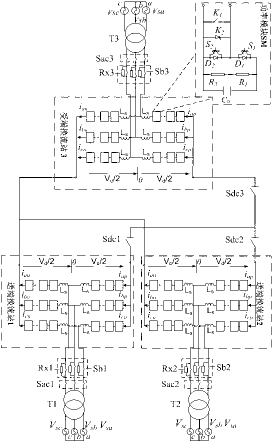
[0037] The structure diagram of the present invention is as figure 1As shown, the multi-terminal flexible DC power transmission system of the present invention includes a first sending-end converter station 1, a second sending-end converter station 2, and a receiving-end converter station 3, and the wind farm is connected to the first sending-end converter station 1 and the second sending-end converter station 2, the first sending-end converter station 1 and the second sending-end converter station 2 convert the electric energy into DC and transmit it to the receiving-end converter station 3 through the DC line, and the receiving-end converter station Station 3 is connected to the large grid after inverting to AC, and the first sending-end converter station 1 is connected to the second sending-end converter station 2 and receiving-end converter station 3 through the DC isolation switch Sdc1, and the second sending-end The converter station 2 is connected to the first sending-e...


PUM


Abstract

The invention is a multi-end flexible direct current transmission system and a starting method thereof. The multi-end flexible direct current transmission system and the starting method thereof comprise two sending end converter stations and a receiving end converter station. A wind power plant is connected with the two sending end converter stations. The two sending end converter stations convert electric energy into direct current and transmit the direct current to the receiving end converter station though a direct current transmission line. The receiving end converter station converts the direct current into alternating current and is connected with a large power network. A first sending end converter station in the two sending end converter stations is connected with a second sending end converter station and the receiving end converter station through a direct current disconnecting switch (Sdc1). The second sending end converter station is connected with the first sending end converter station and the receiving end converter station through a direct current disconnecting switch (Sdc2). The receiving end converter station is connected with the first sending end converter station and the second sending end converter station through a direct current disconnecting switch (Sdc3). The starting procedure of the multi-end flexible direct current transmission system and the starting method thereof is stable and has a safe and reliable property and a wide range of application. The multi-end flexible direct current transmission system and the starting method thereof is used for multi-end flexible direct current transmission projects with modularization multi-end flat topological structures, and can decrease impact current on alternating current side or direct current side at the moment of deblocking of multi-end converter stations, and can stably generate direct voltage to a rated value.

Description

technical field [0001] The invention is a multi-terminal flexible direct current transmission system and a start-up method thereof, belonging to the innovative technology of the start-up method of the multi-terminal flexible direct current transmission system. Background technique [0002] Flexible DC transmission is based on voltage source converter (VSC) and pulse width modulation (PWM) to invert DC voltage into AC voltage with controllable amplitude and phase, and can independently and quickly control the transmitted active power and reactive power. Power, which greatly enhances the flexibility of power transmission, has become the most potential power transmission method to realize the interconnection of regional power grids, large-scale wind farms, and stable connections between AC weak power grids and the main grid. Since ABB's first experimental light direct current transmission project was put into operation in Hellsjon in 1997, more than a dozen light direct current...

Claims


Application Information

Patent Timeline
IPC IPC(8): H02J3/36H02M1/36
CPCY02E10/76Y02E60/60
Inventor 朱喆陈俊饶宏黎小林许树楷
Owner ELECTRIC POWER RESEARCH INSTITUTE, CHINA SOUTHERN POWER GRID CO LTD
Learn More