
Method for adjusting leakage inductance of high-frequency transformer and high-frequency transformer

A high-frequency transformer and high-frequency technology, applied in the electromagnetic field, can solve the problems of increasing the distance, poor magnetic coupling ability, and increasing the volume of the transformer, and achieve the effect of low cost and satisfying requirements.

Inactive Publication Date: 2013-04-24
SHENZHEN AOCI POWER SUPPLY TECH
View PDF3 Cites 4 Cited by
  • Summary
  • Abstract
  • Description
  • Claims
  • Application Information

AI Technical Summary

Problems solved by technology

[0005] When the same type of transformer needs to change the leakage inductance, it needs to be equipped with different special skeletons to match it. The cost of the skeleton mold is high and the versatility is poor.
[0006] If the leakage inductance is to be increased, the distance between the primary and secondary windings must be increased, resulting in increased transformer volume, poor magnetic coupling capability, and low transformer transmission efficiency.
When the resonant inductance is large, the distance between the primary and secondary windings may be increased and still not meet the requirements

Method used


Image

  • Method for adjusting leakage inductance of high-frequency transformer and high-frequency transformer
  • Method for adjusting leakage inductance of high-frequency transformer and high-frequency transformer
  • Method for adjusting leakage inductance of high-frequency transformer and high-frequency transformer

Examples


Embodiment Construction

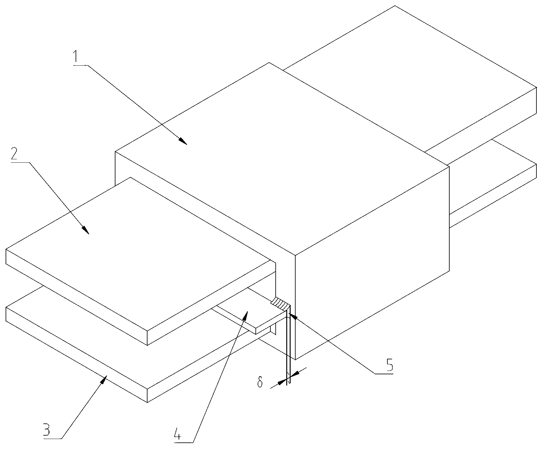
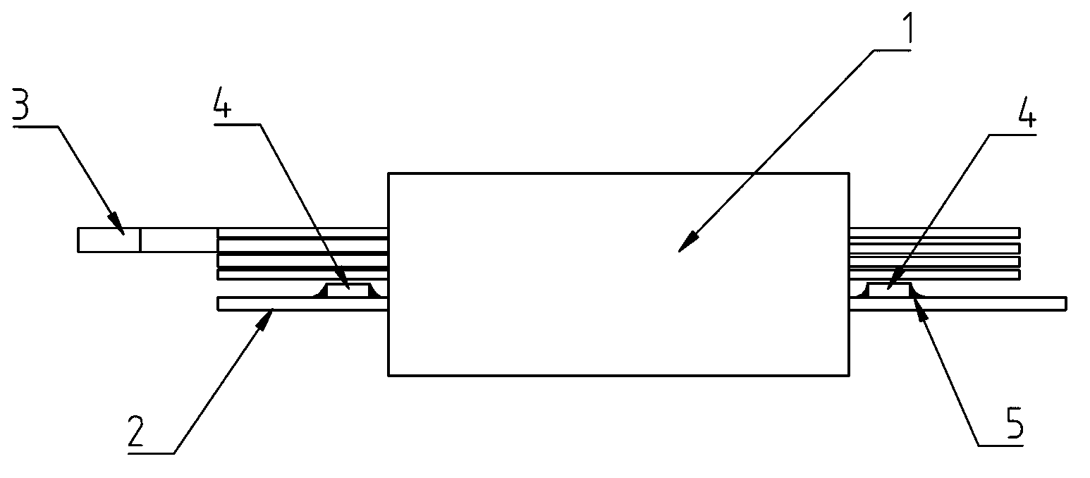
[0027] The high-frequency transformer of embodiment 1 of the present invention such as figure 1 As shown, it includes a magnetic core 1, a primary winding 2, a secondary winding 3 and a high-frequency magnetic strip 4. The high-frequency magnetic strip 4 is arranged between the primary winding 2 and the secondary winding 3, and is located in the high-frequency transformer core 1. The outside of the window is fixed on the magnetic core 1 by an adhesive 5 (such as epoxy resin).

[0028] Magnetic core 1 can be EE, EI, EC, PQ and other power cores; the coil of primary winding 2 can be enameled wire, triple insulated wire, copper foil or PCB; the coil of secondary winding 3 can be enameled wire, triple insulated wire , copper foil or PCB.

[0029] The operating frequency of the high-frequency magnetic strip 4 is as high as 20MHz, and its initial permeability does not decrease at the frequency of 20MHz.

[0030] The material of the high-frequency magnetic strip 4 can be NiZn ferr...


PUM

PropertyMeasurementUnit
Curie temperatureaaaaaaaaaa

Abstract

The invention discloses a method for adjusting leakage inductance of a high-frequency transformer and the high-frequency transformer. The high-frequency transformer comprises a magnetic core, a primary winding, a secondary winding and one or two high-frequency magnetic strips, wherein the high-frequency magnetic strips are distributed between the primary winding and the secondary winding and arranged on the external side of a magnetic core window of the high-frequency transformer; and the high-frequency magnetic strips are arranged on two sides of the magnetic core when two high-frequency magnetic strips are adopted. The high-frequency magnetic strips are inserted into the transformer to achieve the aim of integrating resonance inductors into the transformer. The size of the resonance inductors can be adjusted by controlling the gap between the high-frequency magnetic strips and the magnetic core. Compared with the prior art, one resonance inductor can be reduced for reducing the cost, and the high-frequency transformer is small in size, strong in magnetic coupling, small in electromagnetic interference, high in transmission efficiency, convenient to manufacture and strong in generality.

Description

[technical field] [0001] The invention relates to electromagnetic technology, in particular to a method for adjusting the leakage inductance of a high-frequency transformer and a high-frequency transformer. [Background technique] [0002] When the power supply adopts the resonant topology, a transformer and a resonant inductor are required. There are two general solutions: [0003] 1. The transformer and resonant inductance are separated independently, which not only wastes space, but also makes PCB board wiring complicated and electromagnetic interference large. As a result, the product has low efficiency, large volume, difficulty in passing EMC testing, and high cost. [0004] 2. The resonant inductor is simply integrated in the transformer, and the leakage inductance of the transformer is used as the resonant inductor. The traditional winding method is used to wind the enameled wire on the customized skeleton. The primary winding 2 is placed on one side of the skeleton...

Claims


Application Information

Patent Timeline
IPC IPC(8): H01F27/34H01F27/24H01F27/28H01F7/00H01F1/34
Inventor 龚志良
Owner SHENZHEN AOCI POWER SUPPLY TECH
Learn More