
I-section prestressed reinforced concrete support pile by centrifugal pouring

A prestressed steel bar, centrifugal pouring technology, applied in construction, sheet pile wall, infrastructure engineering and other directions, can solve the problems of poor horizontal and lateral earth pressure mechanical properties, unfavorable saving of building materials resources, surrounding environmental pollution, etc., and achieve construction time. Shorten, improve pile driving efficiency, improve quality and production efficiency

Active Publication Date: 2015-06-17
孔超
View PDF6 Cites 0 Cited by
  • Summary
  • Abstract
  • Description
  • Claims
  • Application Information

AI Technical Summary

Problems solved by technology

[0003] The mechanical properties of its circular section bearing horizontal and lateral earth pressure are poor, which is not conducive to saving building material resources; at the same time, the discharge of drilling mud will cause pollution to the surrounding environment; When protecting piles, construction anti-seepage curtains must be set outside the enclosure piles, and the anti-seepage curtains are usually cement mixing piles or high-pressure jet grouting piles
[0004] Since the anti-seepage curtain is not connected with the surrounding protection piles, the probability of leakage is relatively high

Method used


Image

  • I-section prestressed reinforced concrete support pile by centrifugal pouring
  • I-section prestressed reinforced concrete support pile by centrifugal pouring
  • I-section prestressed reinforced concrete support pile by centrifugal pouring

Examples


Embodiment Construction

[0027] The present invention will be further described in detail below in conjunction with the accompanying drawings and embodiments.

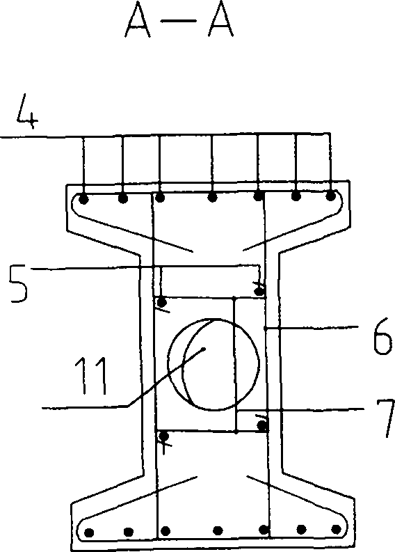
[0028] Figure 1 to Figure 13 An embodiment of the present invention is shown, which includes a standard pile segment 10 with an I-shaped section, and the left and right sides of the I-shaped section are trapezoidal, such as figure 2 Shown; Its trapezoidal slope is 1: 3; This trapezoidal slope is to facilitate demoulding from its two sides after the concrete pouring of said I-shape support pile;

[0029] The circular hole 11 in the center of the I-shaped section is because Figure 13 After the steel form is filled with concrete, the space left by the concrete is completely compacted by high-pressure centrifugal action. The round hole formed by the centrifugal force is the hole left by the centrifugal pouring process, such as figure 2 As shown; the centrifugal force of pouring concrete is zero at the center of the round hole, and gradually ...


PUM


Abstract

An I-section prestressed reinforced concrete support pile by centrifugal pouring comprises a standard pile segment provided with the I-section, the standard pile segment comprises an I-shaped stirrup composed of two triangular reinforcing bars and two vertical reinforcing bars, a steel die is arranged at the geometrical center of the I-shaped stirrup, and concrete is poured into the steel die to the full prior to enabling the concrete to be completely compacted under the high-pressure centrifugation action so that a reserved space forms a centrifugal force round hole. A reinforcement cage formed by connecting a plurality of prestressed reinforcing bars with erection bars through S-shaped stirrups is longitudinally arranged at the upper end and the lower end of the I-shaped stirrup, the steel die is arranged on the periphery of the reinforcement cage, two ends of the prestressed reinforcing bars in the reinforcement cage in the steel die are headed to penetrate into 8-shaped holes of anchor plate holes of an end steel plate, the prestressed reinforcing bars are tensioned to be fixed on end plates of the steel die, the concrete is poured into the steel die, and a steel die top cover covers the steel die before the steel die is placed on a centrifugation table so that the reserved central hole is formed. Bending members bearing lateral soil pressure in foundation pit engineering has the optimal bending section characteristic. The I-section prestressed reinforced concrete support pile by centrifugal pouring has the advantages that pouring quality and concrete strength are high, production efficiency is high, and raw materials of the reinforcing bars, the concrete and the like can be saved greatly.

Description

technical field [0001] The invention relates to a pile foundation of civil construction engineering, in particular to a centrifugal pouring prestressed reinforced concrete I-shaped section support pile used in deep foundation pit engineering and capable of bearing horizontal lateral earth pressure foundation pit enclosure engineering. Background technique [0002] At present, the existing surrounding protection piles usually adopt bored cast-in-situ piles or sinking pipe piles, and the implementation process generally adopts the construction method of cast-in-place piles on the construction site. After the construction of the surrounding protection piles is completed, the The concrete must also reach the required strength before excavating the earthwork in the foundation trench; the construction quality and construction efficiency of such construction method are all low; secondly, the bored pile or immersed pipe pile [0003] The mechanical properties of its circular section...

Claims


Application Information

Patent Timeline
Patent Type & Authority Patents(China)
IPC IPC(8): E02D5/58E02D5/30B28B21/80
Inventor 孔超孔清华
Owner 孔超
Learn More