
Over-voltage protection method for modularized multi-level voltage source commutation valve

A modular multi-level, voltage source commutation technology, applied in emergency protection circuit devices, emergency protection circuit devices, electrical components, etc. for limiting overcurrent/overvoltage, which can solve complex structural design, overvoltage level, etc. It can improve the operation reliability, reduce the overvoltage level, and reduce the insulation level requirements.

Active Publication Date: 2013-04-17
GLOBAL ENERGY INTERCONNECTION RES INST CO LTD +2
View PDF4 Cites 39 Cited by
  • Summary
  • Abstract
  • Description
  • Claims
  • Application Information

AI Technical Summary

Problems solved by technology

[0005] The overvoltage level of the modular multi-level voltage source converter valve in the high-voltage and large-capacity flexible DC system is high, which will lead to problems such as high insulation requirements, high cost, complex structural design, and large floor space. The invention provides a modular The overvoltage protection method of the multi-level voltage source converter valve can be effectively suppressed, the overvoltage level of the voltage source converter valve can be effectively protected, the safe and reliable operation of the voltage source converter valve can be protected under various working conditions, and the voltage source converter can be improved. The technical economy of flow valve

Method used


Image

  • Over-voltage protection method for modularized multi-level voltage source commutation valve
  • Over-voltage protection method for modularized multi-level voltage source commutation valve
  • Over-voltage protection method for modularized multi-level voltage source commutation valve

Examples


Embodiment Construction

[0067] The specific implementation manners of the present invention will be further described in detail below in conjunction with the accompanying drawings.

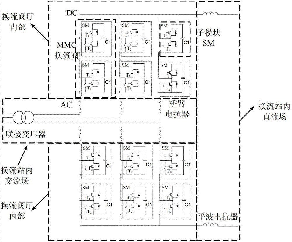
[0068] The structural diagram (single station) of the modular multi-level flexible direct current transmission system provided by the present invention is as follows: figure 1 As shown, the modular multi-level flexible DC transmission system is a three-phase structure, and each phase is composed of two upper and lower bridge arm voltage source converter valves in series; the AC side of the upper and lower bridge arm voltage source converter valves are connected in series There are bridge arm reactors, the bridge arm reactors of the upper and lower bridge arm voltage source converter valves are connected in series, and a connecting transformer is connected between the two bridge arm reactors; on the DC side of the voltage source converter valves of the upper and lower bridge arms There are smoothing reactors connected in ...


PUM


Abstract

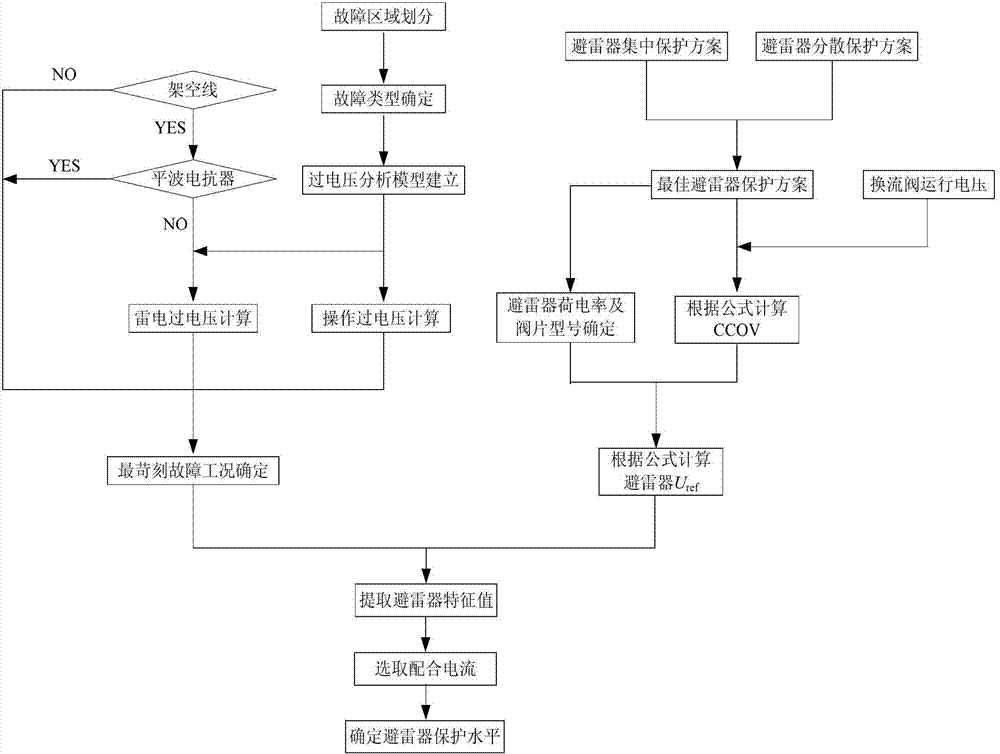
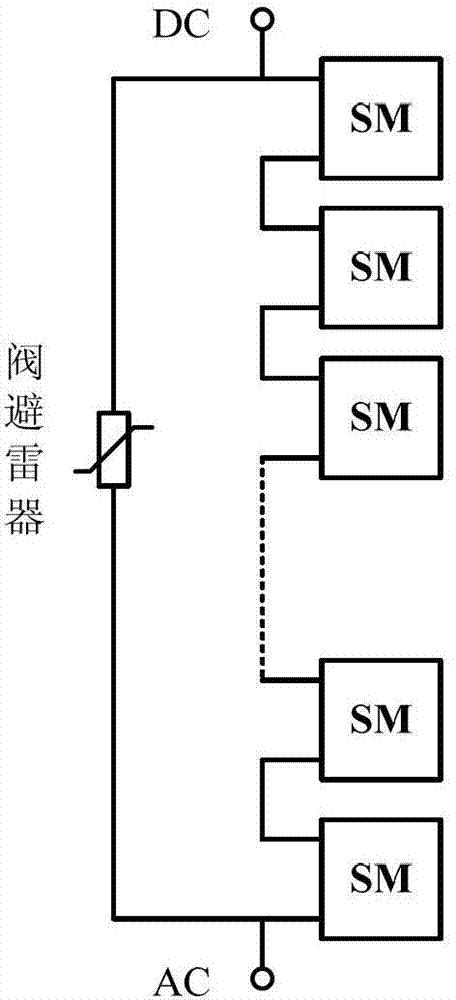
The invention relates to an over-voltage protection method for a modularized multi-level voltage source commutation valve. The over-voltage protection method for the modularized multi-level voltage source commutation valve comprises the following steps of: 1) determining the harshest fault working condition which causes the over-voltage stress of the modularized multi-level voltage source commutation valve; 2) determining the lightning arrester configuration mode of the modularized multi-level voltage source commutation valve; and 3) selecting a lightening arrester parameter. The step (2) of determining the lightning arrester configuration mode of the modularized multi-level voltage source commutation valve comprises the following sub-steps of: (2.1) determining a centralized protection scheme of the lightning arresters; (2.2) determining the dispersive protection scheme of the lightening arresters; (2.3) determining the amount of the lightening arresters of single convertor station; (2.4) determining the working voltage of the lightening arresters; and (2.5) determining an optimal lightening arrester protection scheme. According to the scheme provided by the invention, the over-voltage level of the voltage source commutation valve is effectively inhibited, the safe and effective operation of the voltage source commutation valve under various working conditions is protected, and the technical economy of the voltage source commutation valve is improved.

Description

technical field [0001] The invention relates to the technical field of flexible direct current transmission, in particular to an overvoltage protection method for a modular multilevel voltage source converter valve. Background technique [0002] The modular multi-level voltage source converter valve is a new type of converter valve different from the conventional thyristor valve for DC transmission. It is the core equipment of the MMC topology flexible DC transmission system and is widely used in the flexible DC transmission system. MMC converter valves may suffer from various types of overvoltage intrusion waves generated from AC side faults, DC side faults and lightning strikes during operation. In order to ensure the safe and reliable operation of the MMC converter valve, it is necessary to make its insulation level higher than the overvoltage level. The overvoltage level of the MMC converter valve directly affects the insulation level of the entire flexible DC transmiss...

Claims


Application Information

Patent Timeline
IPC IPC(8): H02H9/04
Inventor 马巍巍李泓志赵岩汤广福王海田
Owner GLOBAL ENERGY INTERCONNECTION RES INST CO LTD
Learn More