
Electronic ballast for hid lamp with multiple protection functions and its pre-excitation method

A technology of electronic ballast and protection function, which is applied in the field of electronic ballast for high-pressure gas discharge lamps, and can solve the problems of low-frequency ignition method without embodiment, non-starting main circuit current, lamp tube gas leakage, etc., and achieves the parameters of components Effects of low sensitivity, reduced ignition voltage, and low starting voltage

Inactive Publication Date: 2015-09-30
HUNAN INTELLIGON SYST
View PDF3 Cites 0 Cited by
  • Summary
  • Abstract
  • Description
  • Claims
  • Application Information

AI Technical Summary

Problems solved by technology

This invention patent has a detailed description of the embodiment of a single MOSFET electronic ballast with DC bias, but there is no embodiment of the widely used high-frequency AC electronic ballast low-frequency ignition method
In addition, when the electronic ballast is used in conjunction with the lamp tube, there may be abnormal conditions such as lamp tube leakage, inactivation, non-start, and excessive current in the main circuit. In order to prevent the ballast from being damaged, this requires the ballast The ignition method has the function of open circuit protection and short circuit protection

Method used


Image

  • Electronic ballast for hid lamp with multiple protection functions and its pre-excitation method
  • Electronic ballast for hid lamp with multiple protection functions and its pre-excitation method
  • Electronic ballast for hid lamp with multiple protection functions and its pre-excitation method

Examples


Embodiment 1

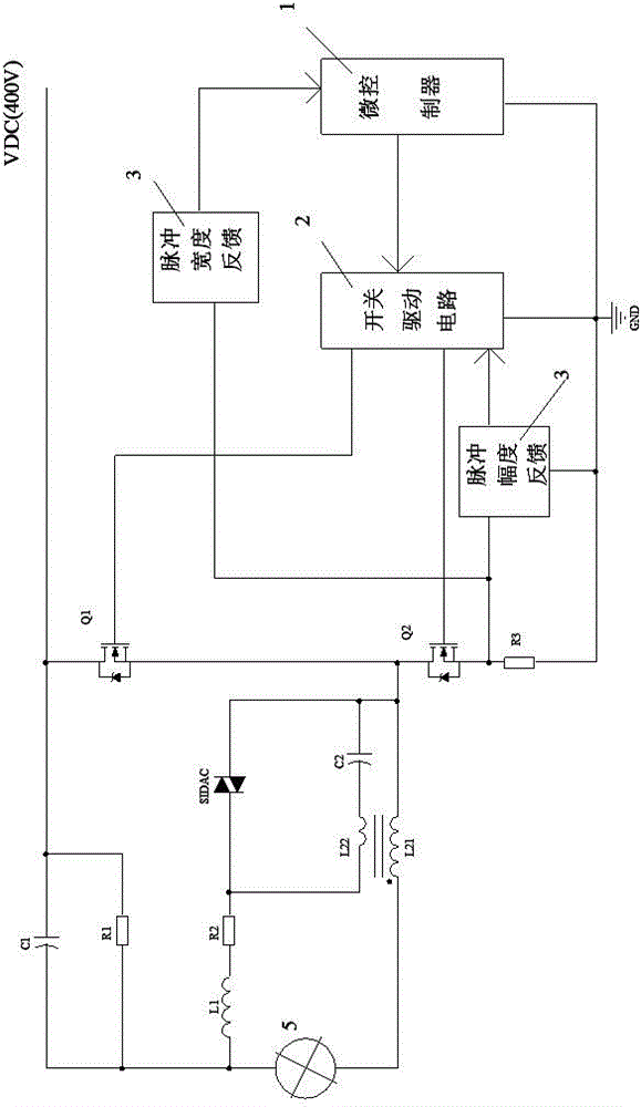
[0034] Such as figure 2As shown, the microcontroller 1 and the switch drive circuit 2 are controlled by the current pulse width and amplitude detection circuit in the feedback circuit 3 respectively. When the lamp is not started, the power switch tube Q2 is turned on and Q1 is turned off, and the power supply VDC charges the capacitor C2 through the resistor R1, inductor L1, resistor R2, inductor L22, power switch tube Q2 and resistor R3; when the voltage on the capacitor C2 exceeds When the trigger voltage of the silicon two-terminal element SIDAC, the silicon two-terminal element SIDAC breaks down, the electric energy on the capacitor C2 generates a reverse electromotive force on the inductor L22 through the breakdown of the silicon two-terminal element SIDAC; due to the turn of the inductor L22 and the main inductor L21 It is relatively large, so the induced high voltage is generated on the main inductor L21 and finally applied to both ends of the HID lamp 5; when the HID ...

Embodiment 2

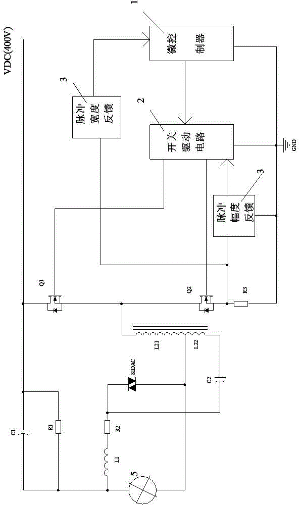
[0043] Such as image 3 and Figure 7 As shown, compared with Embodiment 1, the self-coupling inductors L21 and L22 are changed. In this example, the inductors with a center tap are used as the autocoupling inductors L21 and L22. The specific connection method of the circuit is as follows: capacitor C1 and resistor R1 are connected in parallel, one end of the parallel connection is connected to one end of inductor L1 and one end of HID lamp 5, and the other end is connected to VDC; one end of the inductor L21 is connected to one end of inductor L22, and the silicon two-terminal element One end of the SIDAC is connected to one end of the lamp 5, the other end of the inductor L21 is connected to one end of the power switch tube Q1 and one end of the power switch tube Q2, the other end of the inductor L22 is connected to one end of the capacitor C2, and the other end of the silicon two-terminal element SIDAC One end is connected to the other end of the resistor R2 and the other ...

Embodiment 3

[0045] Such as Figure 4 and Figure 8 As shown, compared with Embodiment 2, the ignition trigger device is changed, and the silicon two-terminal element SIDAC trigger is replaced by a thyristor trigger circuit. The thyristor trigger circuit includes: capacitor C21, resistor R4, resistor R5, low-voltage silicon two-terminal element D303, and thyristor SCR. The working principle of the circuit ignition trigger is as follows: when the ignition circuit is working, VDC forms a loop through resistors R1, R2, R3, R4, R5, inductors L1, L21 and power switch tube Q2, when the voltage on resistor R5 exceeds the trigger voltage of D303 ( 28V~32V), D303 is turned on, thereby triggering the thyristor SCR, which is to replace the function of the silicon two-terminal element SIDAC in Embodiment 2. Other parts of the working principle are the same as in Embodiment 2.


PUM


Abstract

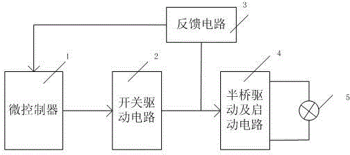
The invention relates to an HID (High Intensity Discharge) lamp electronic ballast with a plurality of protection functions, which comprises a microcontroller, a switch drive circuit, a feedback circuit and a half-bridge drive and start-up circuit, wherein the microcontroller generates pulse sequence signals, and controls the circuit operation; the switch drive circuit provides drive signals to the half-bridge drive and start-up circuit; the feedback circuit returns the width and amplitude change of current signals to the microcontroller; and the half-bridge drive and start-up circuit adopts a low-frequency pulse ignition mode with open circuit and short circuit protection functions to start and drive an HID lamp. The electronic ballast has the open circuit and electrified tube replacement functions, the short circuit protection function during starting and the function of preventing the HID lamp from generating sound oscillation, so that the reliability is largely improved. And in addition, the invention further provides a general pre-exciting method for reducing ignition voltage of the HID lamp electronic ballast; and the method reduces the ignition voltage of the HID lamp.

Description

technical field [0001] The invention relates to an electronic ballast, in particular to an electronic ballast for a high-pressure gas discharge lamp with pre-excitation function, multiple protection functions and low-frequency ignition. Background technique [0002] HID lamp (High Intensity Discharge Lamp) is a new generation of high-efficiency lighting source widely used at present, it has the characteristics of high power, high light efficiency and long life. It requires a higher starting voltage than fluorescent lamps. At present, electronic ballasts for low-power HID lamps generally use LC resonance ignition to start at home and abroad, and electronic ballasts for high-power HID lamps mostly use the control of driver chips to achieve resonance ignition. The starting voltage of resonant ignition is related to the Q value of the resonant circuit. For HID lamps with extremely nonlinear dynamic characteristics, it is difficult to accurately control the starting voltage, and...

Claims


Application Information

Patent Timeline
Patent Type & Authority Patents(China)
IPC IPC(8): H05B41/292
CPCY02B20/208Y02B20/00
Inventor 周锋龚明甫廖粤武
Owner HUNAN INTELLIGON SYST
Learn More