
Device of monitoring fissure deep fracture development by using geological radar and monitoring method

A geological radar and deep-seated technology, applied in geophysical surveying, instruments, etc., can solve the problems of high cost, poor precision, and inability to record, and achieve the effect of easy data and simple operation

Inactive Publication Date: 2013-04-10
SHANDONG UNIV
View PDF4 Cites 9 Cited by
  • Summary
  • Abstract
  • Description
  • Claims
  • Application Information

AI Technical Summary

Problems solved by technology

[0003] The safety monitoring research of dangerous rock mass has a long history, and there are many monitoring methods. The traditional method adopts the intuitive micrometer observation method, which is to directly measure the crack width change of dangerous rock mass with a micrometer. The measurement method is intuitive and simple. However, there are problems such as poor accuracy and inability to record
With the further development of science and technology, GPS and INSAR three-dimensional laser scanners have also been introduced into the safety detection of dangerous rock masses. Although the data collection is convenient, the accuracy still cannot meet the monitoring requirements, and the cost is expensive. In the engineering application, it can not play a very good role in monitoring and predicting the collapse of dangerous rock mass.
Moreover, the above-mentioned methods only reflect the collapse trend of dangerous rock masses by detecting the displacement changes of the upper part of the cracks, etc., and do not propose any scientific monitoring means for the development of deep cracks in the cracks that directly cause the collapse of dangerous rock masses.

Method used


Image

  • Device of monitoring fissure deep fracture development by using geological radar and monitoring method

Examples


Embodiment Construction

[0015] The present invention will be further described below in conjunction with the drawings and embodiments.

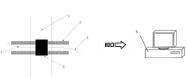
[0016] Such as figure 1 As shown, in the crack 1 to be measured, a slide rail 2 of appropriate length is installed along the width of the crack. A horizontal connecting frame that can slide along the slide rail and a geological radar 3 is installed between the two slide rails. The geological radar is fixedly installed at On the horizontal connecting frame, the geological radar equipment collects the data of the deep crack development along the slide rail 2; the left and right ropes 4 are controlled to make the geological radar slide along the slide rail 2, and the geological radar is controlled to collect data, and the collected data Transmit to the computer 5; use the computer 5 to comprehensively process and judge the data collected from multiple measuring points to determine the development of the deep fractures; according to the relevant judgment criteria, the comp...


PUM


Abstract

The invention discloses a device of monitoring fissure deep fracture development and forecasting dangerous rock body collapse by using geological radar. The device of monitoring the fissure deep fracture development and forecasting the dangerous rock body collapse by using the geological radar comprises a sliding rail which is installed along the width direction of a dangerous rock body fracture, wherein the sliding rail is provided with a horizontal link span which can move along the sliding rail, the geological radar is fixedly installed on the horizontal link span, two sides of the geological radar is connected with ropes, and the geological radar is connected with a computer. The invention further discloses a monitoring method by using the device of monitoring the fissure deep fracture development and forecasting the dangerous rock body collapse by using the geological radar. The device of monitoring the fissure deep fracture development and forecasting the dangerous rock body collapse by using the geological radar and the monitoring method make use of contactless and long-distance detection features of the geological radar, efficiently achieve monitoring of dangerous rock body fissure deep fracture development, then achieve collapse forecasting of a dangerous rock body according to developmental situation and change features of the dangerous rock body and combination of relative judging criteria, and have the advantages of being simple in operation, prone to data record, efficient, accurate and the like.

Description

[0001] Technical field [0002] The invention relates to a rock mass collapse prediction device and method, in particular to a device and a monitoring method for monitoring the development of deep cracks by using geological radar. Background technique [0003] The safety monitoring of dangerous rock masses has a long history, and there are many monitoring methods. The traditional method adopts the intuitive micrometer observation method, which is to directly measure the crack width change of the dangerous rock mass with a micrometer. The measurement method is intuitive and simple. However, there are problems such as poor accuracy and inability to record. With the further development of science and technology, GPS, INSAR 3D laser scanners, etc. have also been introduced into the safety inspection of dangerous rock masses. Although the data collection is convenient, the accuracy still cannot meet the monitoring requirements well, and the cost is expensive. In the engineering applic...

Claims


Application Information

Patent Timeline
IPC IPC(8): G01V9/00
Inventor 李术才薛翊国张乐文徐咸辉张骞田昊宁凯闫茂旺
Owner SHANDONG UNIV
Learn More