Butterfly valve drive hydraulic cylinder with locking device

A locking device, hydraulic cylinder technology, applied in valve device, valve operation/release device, device to prevent accidental or unauthorized action, etc. Unreasonable installation location and structure, etc., to achieve the effect of reasonable location and structure

Inactive Publication Date: 2013-04-10
TIELING VALVE
View PDF3 Cites 0 Cited by
  • Summary
  • Abstract
  • Description
  • Claims
  • Application Information

AI Technical Summary

Problems solved by technology

[0005] This kind of butterfly valve closing state locking device will drive the hydraulic cylinder hydraulic system and components to fail, or operate incorrectly, the piston rod of the hydraulic cylinder will protrude, and the force will be applied to the positioning bolt on the body of the butterfly valve through the connecting rod body. The driving force of the hydraulic cylinder is relatively large. The above faults or misoperations are likely to cause damage to the butterfly valve body, the foundation of the butterfly valve or the pipeline connected to the butterfly valve through the positioning bolts on the butterfly valve body.
The installation position and structure of the butterfly valve closed state locking device are very unreasonable

Method used


Image

  • Butterfly valve drive hydraulic cylinder with locking device
  • Butterfly valve drive hydraulic cylinder with locking device
  • Butterfly valve drive hydraulic cylinder with locking device

Examples


Embodiment Construction

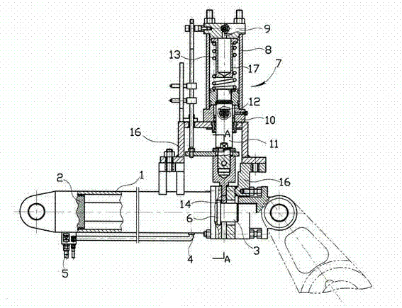
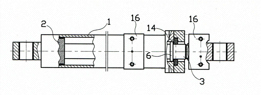
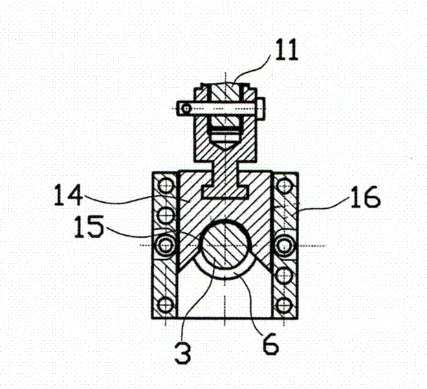
[0019] Figure 1~Figure 3 Among them, the butterfly valve-driven hydraulic cylinder with locking device has a cylinder body 1, a piston 2 in the cylinder body, and a piston rod 3 extending out from the front end of the cylinder body connected to the piston. The hydraulic medium inlet and outlet 4, 5, the limit ring 6 on the front section of the rod body where the piston rod extends out of the cylinder body, the upper part of the front end of the cylinder body is connected with a locking hydraulic cylinder 7 whose axis is perpendicular to the axis of the cylinder body through a bracket 16, and the locking hydraulic pressure Cylinder has cylinder body 8, and the upper end of cylinder body and the lower end are connected with cylinder head 9,10 respectively, and the piston rod 11 that links to each other with piston in cylinder body stretches out from lower cylinder head, and the lower cylinder head has the valve that communicates with cylinder cavity. The hydraulic medium inlet ...


PUM


Abstract

The invention discloses a butterfly valve drive hydraulic cylinder with a locking device. A limiting ring is arranged on a front section of a rod body of a piston rod, which extends out of a cylinder body, a vertical locking hydraulic cylinder is connected above the front end of the cylinder body, an inlet and an outlet are formed in a lower cylinder cover, a spring is arranged between a piston and the upper cylinder cover in the cylinder body, the lower end of the piston rod, which extends out of the lower cylinder cover, is connected with a fork locking plate, and when the piston rod of the drive hydraulic cylinder is retracted and the piston rod of a locking hydraulic cylinder extends out downwards, a semi-round hole of the fork locking plate is propped against the front side of the limiting ring on the piston rod of the drive hydraulic cylinder. The drive hydraulic cylinder is connected with the locking hydraulic cylinder, and the lower end of the piston rod of the locking hydraulic cylinder is connected with the fork locking plate, so that a closed butterfly valve can be in a locking state. Once a hydraulic system and elements of the drive hydraulic cylinder fail to work or are falsely operated and the piston rod of the drive hydraulic cylinder is caused to tend to extend out, a butterfly valve body, a butterfly valve foot base or a pipeline which is connected with the butterfly valve cannot be damaged, and the butterfly valve closing state locking device is reasonable in position and structure.

Description

technical field [0001] The invention relates to a hydraulic cylinder driven by a butterfly valve, in particular to a closing and locking device for a hydraulic cylinder driven by a butterfly valve. Background technique [0002] Large-diameter butterfly valves need to be driven by hydraulic cylinders to open and close. A connecting rod body is connected between the piston rod of the hydraulic cylinder that drives the opening and closing of the butterfly valve and the valve shaft. When the piston rod of the hydraulic cylinder is extended, the butterfly valve is opened through the connecting rod body. When the piston rod of the hydraulic cylinder is retracted, the butterfly valve is closed through the connecting rod body. . [0003] When the pipe fittings downstream of the butterfly valve need to be repaired, the hydraulic cylinder must be used to drive the butterfly valve to close, so that maintenance personnel can safely perform maintenance work on the pipe fittings in or ar...

Claims


Application Information

Patent Timeline
Patent Type & Authority Applications(China)
IPC IPC(8): F16K31/122F16K35/00
Inventor 李延辉姚化新李凯艳
Owner TIELING VALVE
Why Eureka
Try Eureka