mobile restraint device

A technology of movement suppression and moving components, which is applied to furniture parts, household appliances, drawers, etc., and can solve problems such as impracticability

Inactive Publication Date: 2015-07-29
NIFCO INC +1
View PDF5 Cites 0 Cited by
  • Summary
  • Abstract
  • Description
  • Claims
  • Application Information

AI Technical Summary

Problems solved by technology

[0005] However, in the conventional structure, it is impossible to suppress the inertia running of the pull-out member and stop the pull-out member at an arbitrary position.

Method used


Image

  • mobile restraint device
  • mobile restraint device
  • mobile restraint device

Examples


Embodiment Construction

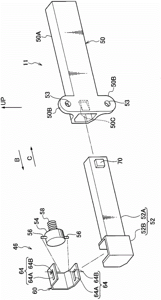
[0029] according to Figure 1 to Figure 10 An example of the movement suppressing device according to the embodiment of the present invention will be described. It should be noted that the arrow UP indicates the upward direction of the cabinet.

[0030] (the whole frame)

[0031] Such as image 3 As shown, the movement suppressing device 11 of this embodiment is fixed to a side wall portion 12A of a cabinet 12 (hereinafter referred to as cabinet 12 ) as an example of a box body, and is provided on the side wall portion 12A and a drawer that can be pulled out from the cabinet 12 freely. between the side walls 14C of the exit member 14. Moreover, at the front portion 14A of the pull-out member 14 ( image 3 The left end shown) is provided with a plate-like paneling 16 . And, the drawer member 14 is supported by the cabinet 12, and is stored in the storage position of the cabinet 12 along the guide rails (not shown) provided on the inner surfaces of the left and right side w...


PUM


Abstract

Provided is a movement-restricting device that can restrict the inertial movement of a drawer component and cause the drawer component to stop at optional positions. When a user grasps the opened end panel (16) and draws the end panel (16) out, the moving component (52) of the movement-restricting device (11) that is adhering to a protruding part (44B) by the magnetic force of a magnetic component is drawn out of the cylinder of a fixed component (50). When the moving component (52) is drawn out of the cylinder a prescribed distance (40 mm), a projection from the part that is drawn out abuts a stop in the cylinder, limiting the movement of the moving component (52) and the moving component is stopped. Inertial movement of the drawer component (14) is thereby restricted and the drawer component (14) can be made to stop at optional positions.

Description

technical field [0001] The present invention relates to a movement suppression device. Background technique [0002] In the structure described in Patent Document 1 (Japanese Unexamined Patent Publication No. 2008-278985 ), the magnetic body of the pull-out member that can be pulled out from the main body and the magnetic body provided at the contact portion of the main body are mutually pulled by magnetic force. And, when the pull-out member is pulled out from the storage position stored in the main body, the abutting portion drawn by the pull-out member moves by magnetic force. [0003] disclosure of invention [0004] The problem to be solved by the invention [0005] However, in the conventional configuration, it is impossible to suppress the coasting of the pull-out member and stop the pull-out member at an arbitrary position. Contents of the invention [0006] An object of the present invention is to suppress the coasting of the pull-out member and stop the pull-o...

Claims


Application Information

Patent Timeline
Patent Type & Authority Patents(China)
IPC IPC(8): A47B88/04
CPCA47B88/04A47B88/473A47B88/40A47B88/477
Inventor 木村元彦山本琢磨
Owner NIFCO INC
Why Eureka
Try Eureka