
Single-pole flux reverse permanent magnet linear motor

A permanent magnet linear motor and magnetic flux reversal technology, which is applied in the direction of electrical components, electromechanical devices, electric components, etc., can solve the problems of low power factor, power density and efficiency, poor fault tolerance performance, and high energy index, and achieve The effect of improving reliability and operating capability with faults, reducing manufacturing costs, and improving utilization

Inactive Publication Date: 2013-04-03
JIANGSU UNIV
View PDF4 Cites 6 Cited by
  • Summary
  • Abstract
  • Description
  • Claims
  • Application Information

AI Technical Summary

Problems solved by technology

Linear motors are divided into two categories: one is electric excitation motor based on linear induction motor, and its defects are: power factor, power density and efficiency are not high; the other is permanent magnet linear synchronous motor. Magneto, compared with linear induction motor, has higher power index, smaller size and lighter weight
[0009] The patent number is CN201010120847.5 "a kind of fault-tolerant permanent magnet linear motor". By introducing isolation teeth into the ordinary magnetic flux reverse permanent magnet motor, the phases are physically isolated and the magnetic circuit is decoupled, which solves the traditional The problem of poor fault tolerance performance of the flux reversal motor
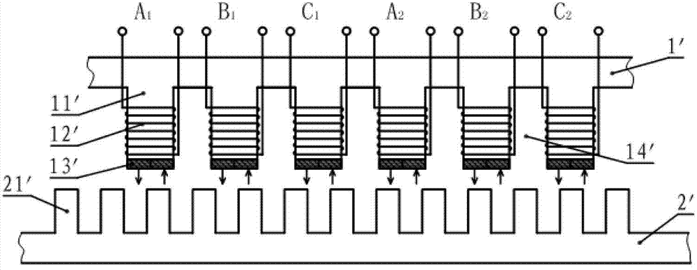
However, it does not fundamentally solve the serious problem of magnetic flux leakage: two permanent magnets with opposite excitation directions are mounted on the surface of its armature teeth, so that a large number of magnetic lines of force do not pass through the yoke of the mover to form a magnetic circuit. Causes the phenomenon of magnetic circuit short circuit, resulting in serious magnetic flux leakage

Method used


Image

  • Single-pole flux reverse permanent magnet linear motor
  • Single-pole flux reverse permanent magnet linear motor
  • Single-pole flux reverse permanent magnet linear motor

Examples


Embodiment Construction

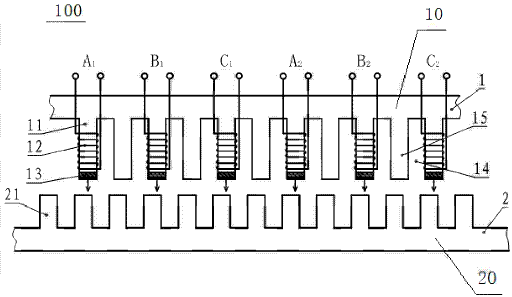
[0031] see figure 2 , figure 2 The structure of the single-pole magnetic flux inversion permanent magnet linear motor according to the embodiment of the present invention is shown.

[0032] The single-pole magnetic flux reversal permanent magnet linear motor 100 includes a mover 1 with a salient pole structure and a stator 2 with a salient pole structure. The mover is composed of a primary iron core 10 , an armature winding 12 and a permanent magnet 13 . The stator is composed of a secondary iron core 20 made of magnetically permeable material.

[0033] There is no winding or permanent magnet on the secondary iron core 20 , and there are multiple salient pole teeth 21 on the secondary iron core 20 .

[0034] The primary iron core 10 is provided with alternately arranged armature teeth 11 and tolerance teeth 15, and slots 14 are formed between the teeth, and the width of all the teeth is the same as the slot width.

[0035] The armature windings 12 are wound on the armatur...


PUM


Abstract

The invention relates to a single-pole flux reverse permanent magnet linear motor, and aims to provide a leakage flux reduced type single-pole flux reverse permanent magnet linear motor with high fault freedom and low manufacturing cost. According to the technical scheme, the single-pole flux reverse permanent magnet linear motor comprises a rotor in a concave pole structure and a stator in a convex pole structure; the rotor consists of a primary iron core, an armature winding and permanent magnets; the stator consists of a secondary iron core; the secondary iron core is made of a magnetic permeability material; the primary iron core is composed of a plurality of fault-tolerant teeth and armature teeth which are arranged alternately; the armature winding is wound on the armature teeth by using a concentrated winding; one permanent magnet is adhered at the end part of each armature tooth; and excitation directions of the permanent magnets at the end parts of the armature tooth are the same.

Description

technical field [0001] The invention relates to a motor, in particular to a magnetic flux reversal permanent magnet linear motor applied to rail traffic. Background technique [0002] With the acceleration of the world's urbanization process, traffic problems have increasingly become a difficult problem for urban development. Urban rail transit vehicles such as subways, light rails, and trams have been applied and developed to varying degrees. Among them, the research and development of the traction motor has become the key to the technical problems of rail transit. [0003] In terms of technology, earlier, the rail transportation system was driven by a rotating motor. It has been used in rail transportation for a long time due to its simple structure, mature technology, and large carrying capacity. However, its physical adhesion limits the acceleration and deceleration performance. , and the disadvantages of large mechanical vibration and noise, lightweight vehicle struct...

Claims


Application Information

Patent Timeline
IPC IPC(8): H02K41/03
Inventor 赵文祥吉敬华严淑君刘国海康梅陆继远
Owner JIANGSU UNIV
Learn More