
Low-profile mobile terminal antenna

A mobile terminal antenna, low-profile technology, applied to antennas, devices that make antennas work in different frequency bands at the same time, radiating element structures, etc. , the effect of small height and simple structure

Inactive Publication Date: 2013-04-03
SHANGHAI AMPHENOL AIRWAVE COMM ELECTRONICS CO LTD
View PDF3 Cites 15 Cited by
  • Summary
  • Abstract
  • Description
  • Claims
  • Application Information

AI Technical Summary

Problems solved by technology

[0003] The purpose of the present invention is to provide a low-profile mobile terminal antenna to solve the technical problems that the resonance bandwidth of the antenna in the prior art is generally narrow and the total radiation efficiency is low

Method used


Image

  • Low-profile mobile terminal antenna
  • Low-profile mobile terminal antenna
  • Low-profile mobile terminal antenna

Examples


Embodiment Construction

[0024] The present invention will be described in detail below in conjunction with the accompanying drawings.

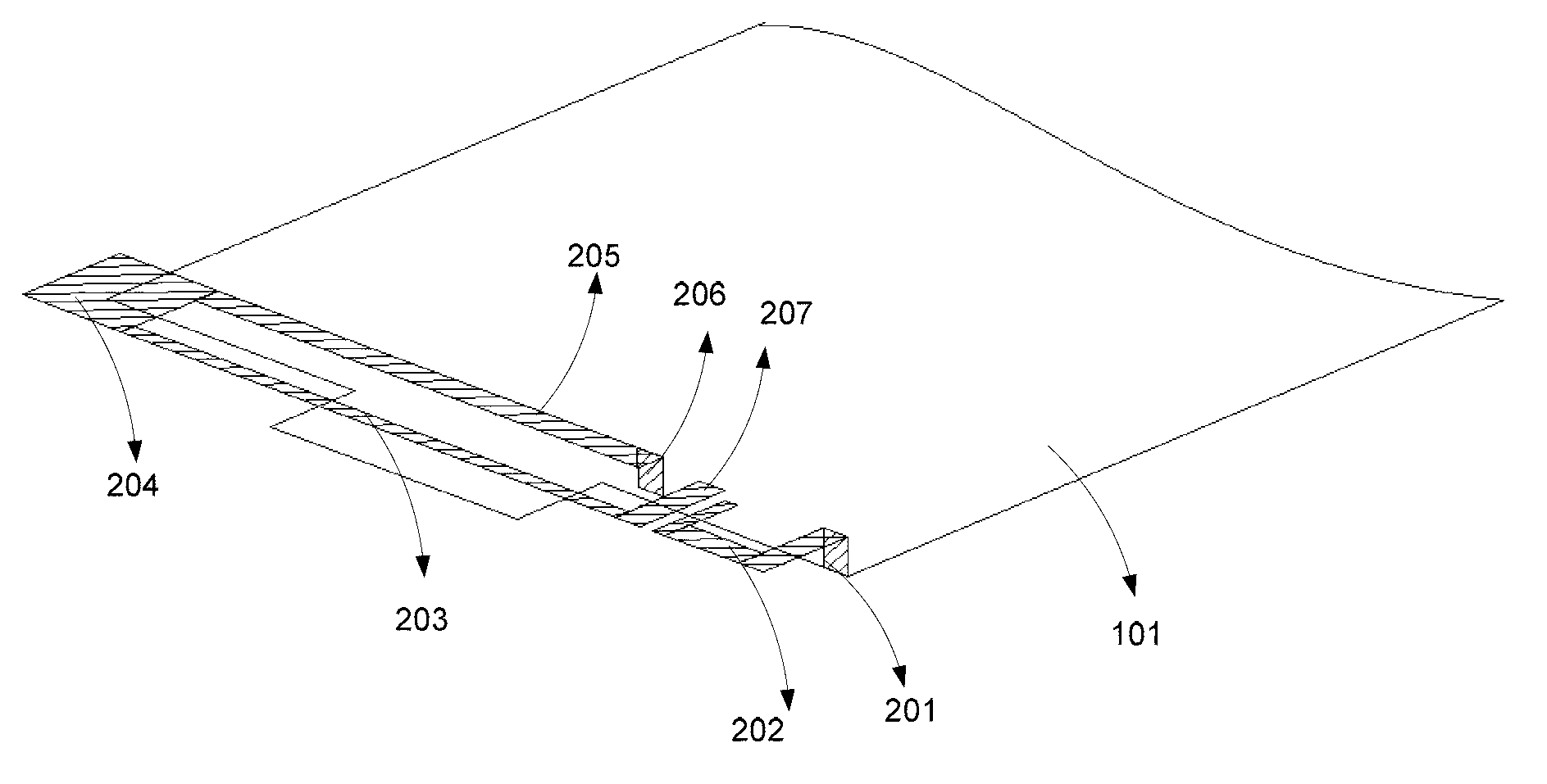
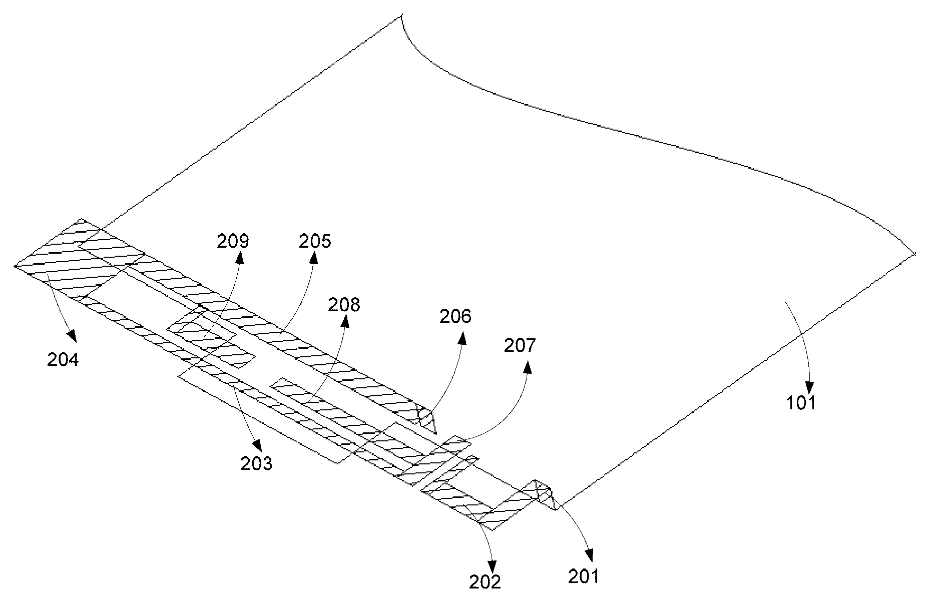
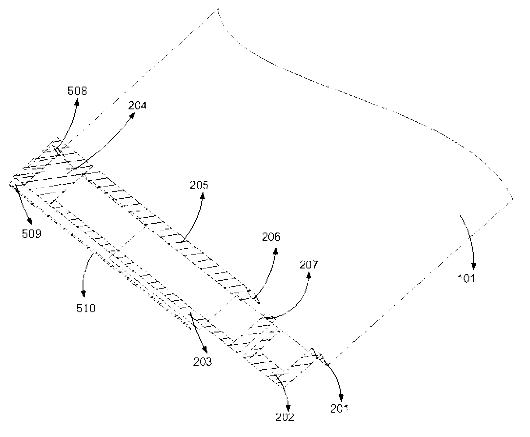
[0025] see figure 1 , is the first embodiment of the low-profile mobile terminal antenna of the present invention, including a PCB board 101 and an antenna body disposed above it, and the antenna body includes a first antenna body and a second antenna body. The first antenna body includes a feed branch 207, a first long branch 203, a second short branch 204, a third long branch 205 and a first ground branch 206 connected in sequence, the feed branch 207, the first long branch 203, the second The short branch 204 , the third long branch 205 and the first ground branch 206 form a loop antenna body, and the feed branch 207 and the first ground branch 206 are respectively connected to the PCB board 101 . The second antenna body includes a second ground branch 201 and a fourth branch 202, and the second ground branch 201 is respectively connected with the fourth branch 2...


PUM


Abstract

The invention relates to a built-in antenna of a mobile terminal, in particular to a low-profile mobile terminal antenna. The low-profile mobile terminal antenna comprises a PCB (printed circuit board) and an antenna body arranged above the PCB, wherein the antenna body comprises a first antenna body and a second antenna body, the first antenna body comprises a feed branch, a first long branch, a second short branch, a third long branch and a first ground branch, the feed branch and the first ground branch are respectively connected with the PCB, the second antenna body comprises a second ground branch and a fourth branch, and the second ground branch is connected with the fourth branch and the PCB. Compared with the prior art, the low-profile mobile terminal antenna is wide in resonance bandwidth, in particular high-frequency bandwidth, and is obvious high in radiant efficiency.

Description

technical field [0001] The invention relates to a built-in antenna of a mobile terminal, in particular to a low profile mobile terminal antenna. Background technique [0002] An antenna is a device that uses frequency characteristics to receive and transmit signals. In recent years, the design and performance of mobile terminal antennas for wireless communication have more and more influence on the development direction of mobile communication. The main indicators of antenna design include: suitable multi-frequency resonance; the antenna realizes signal propagation and energy radiation based on resonance of a certain frequency. If an antenna can resonate at multiple frequencies, then the antenna will work at multiple frequencies. On the other hand, the design of mobile terminals is becoming more and more highly integrated, resulting in smaller and smaller space occupied by the antenna. For the antenna, an important dimension is the height of the antenna, because mobile te...

Claims


Application Information

Patent Timeline
Patent Type & Authority Applications(China)
IPC IPC(8): H01Q1/36H01Q5/01H01Q5/10
Inventor 尹海杰孙劲何其娟
Owner SHANGHAI AMPHENOL AIRWAVE COMM ELECTRONICS CO LTD
Learn More