Angle switch

A switch and angle technology, applied in the direction of electric switches, electrical components, circuits, etc., can solve the problems of small contact surface, small range of conduction current, poor current stability, etc., so as to increase the service life and increase the on-off The effect of increasing the amount of current and increasing the application range

Inactive Publication Date: 2013-04-03
上海海连电动工具有限公司
View PDF5 Cites 2 Cited by
  • Summary
  • Abstract
  • Description
  • Claims
  • Application Information

AI Technical Summary

Problems solved by technology

[0006] The purpose of the present invention is to provide an angle switch to solve the problems in the prior art that the contact surface of the ball switch is small, the current stability is poor, and the range of the conduction current is small

Method used


Image

  • Angle switch
  • Angle switch

Examples


Embodiment Construction

[0019] In order to make the technical means, creative features, objectives and effects achieved by the present invention easy to understand, the present invention will be further described below in conjunction with specific embodiments.

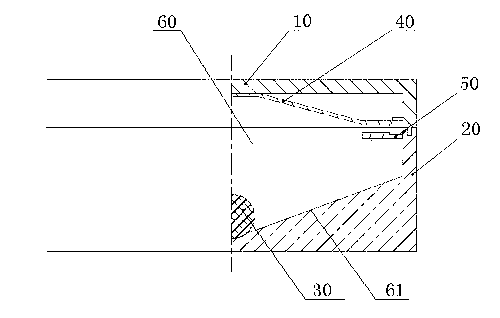
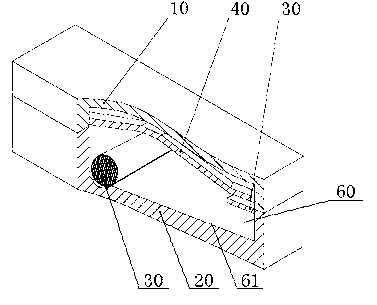
[0020] Such as figure 1 and figure 2 As shown, the angle switch of the present invention includes a switch housing, and the switch housing includes a switch upper housing 10, a switch lower housing 20, a magnetic roller 30, a first attached electrode piece 40 and a second attached electrode sheet 50, the switch upper case 10 and the switch lower case 20 are matched to form an accommodating space 60, the magnetic roller 30 is arranged in the accommodating space 60, the first additional electrode sheet 40 and the second additional electrode sheet 40 The electrode pieces 50 are arranged in the switch upper case 10 and the switch lower case 20 respectively corresponding to each other.

[0021] In the present invention, the bottom of the accomm...


PUM


Abstract

The invention discloses an angle switch which comprises an upper switch shell, a lower switch shell and a magnetic pin roller. The upper switch shell and the lower switch shell are matched to form a containing space, the magnetic pin roller is arranged in the containing space, and a first electrode plate and a second electrode plate are arranged on the upper switch shell and the lower switch shell correspondingly. By means of the angle switch, the problems of small breakover current range, poor current stability and small contact surface of contacts of ball switches in the prior art are solved. By using the magnetic pin roller to substitute a common ball, contact area is greatly increased, on-off current magnitude is increased, application range of the switch is widened, and the service life of the switch is prolonged.

Description

technical field [0001] The invention relates to an angle switch, in particular to an angle switch suitable for conducting and disconnecting electrical circuits. Background technique [0002] At present, there are many kinds of angle switches used in various fields, among which the ball switch is the most commonly used one and is widely used in various fields. [0003] In the existing ball switch, through the rolling of the balls in the switch, the contact and separation with the metal terminal is produced, and the effect of conducting or not conducting electric energy is generated. [0004] However, because the existing ball switch conducts the circuit through contact, not only the contact stability is not good enough, it is easy to cause current fluctuations, and the conduction current can only be limited to a small range. [0005] Therefore, it is particularly necessary to provide an angle switch to solve the above problems. Contents of the invention [0006] The objec...

Claims


Application Information

Patent Timeline
Patent Type & Authority Applications(China)
IPC IPC(8): H01H35/02
Inventor 史晓军
Owner 上海海连电动工具有限公司
Why Eureka
Try Eureka