
Method for calculating radar scattering cross section of metal cylindrical calibration body

A radar cross-section and metal cylinder technology, applied in radio wave measurement systems, instruments, etc., can solve problems such as limitations of existing technologies

Active Publication Date: 2013-04-03
BEIHANG UNIV
View PDF3 Cites 11 Cited by
  • Summary
  • Abstract
  • Description
  • Claims
  • Application Information

AI Technical Summary

Problems solved by technology

[0011] There are at least the following problems in the prior art: the existing empirical formula is only applicable to the calculation of the total scattered electric field of a given metal cylinder calibration body whose height-to-diameter ratio of the metal cylinder is 0.4667, and the given ka>25 Fixed metal cylinder calibration body, and is not applicable to the RCS calculation of the given metal cylinder calibration body where the ratio of the height to diameter of the metal cylinder is other values, and ka<25
These problems make the existing technology severely limited in practical engineering applications

Method used


Image

  • Method for calculating radar scattering cross section of metal cylindrical calibration body
  • Method for calculating radar scattering cross section of metal cylindrical calibration body
  • Method for calculating radar scattering cross section of metal cylindrical calibration body

Examples


Embodiment Construction

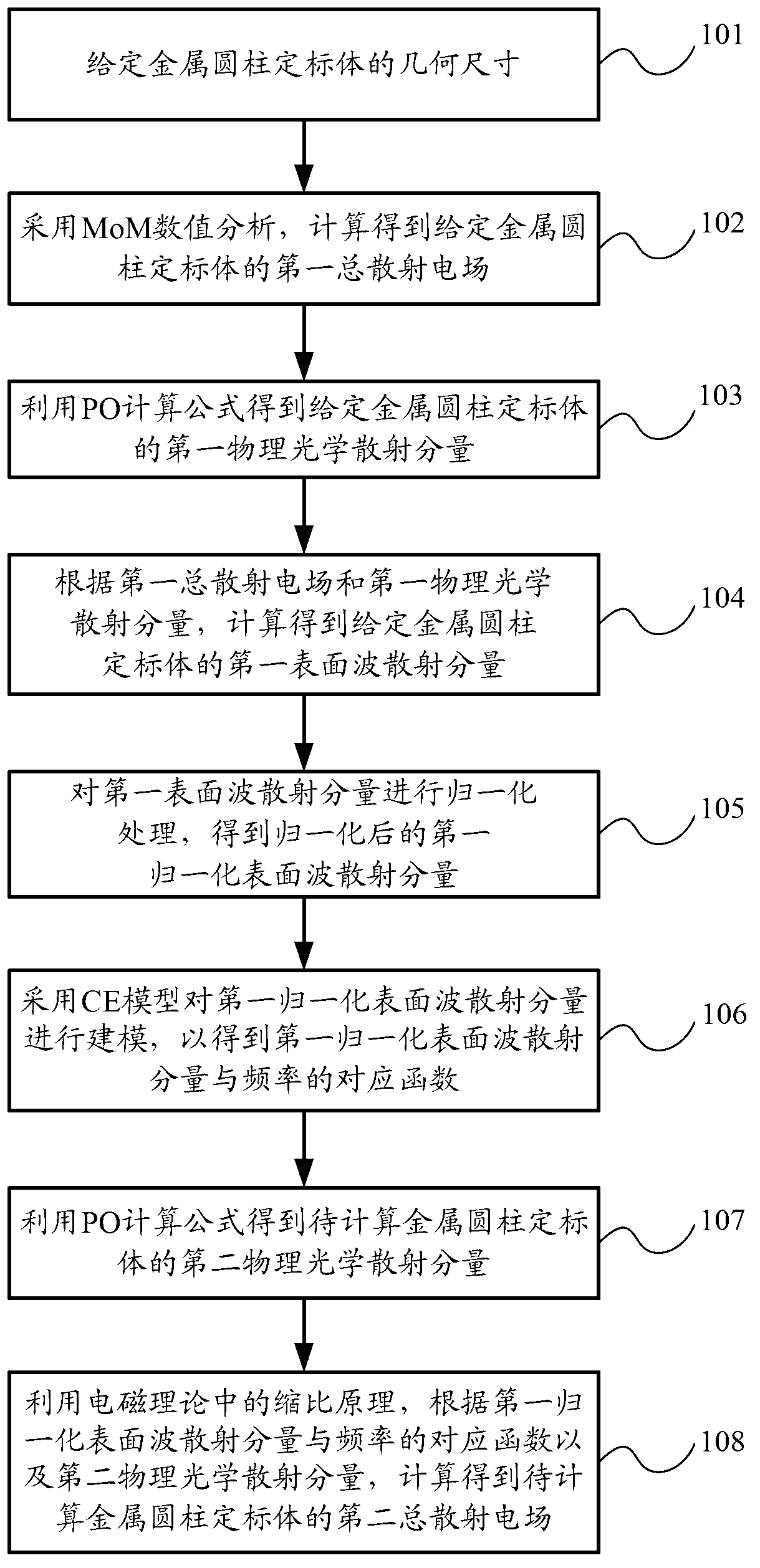
[0043] figure 1 It is a flow chart of an embodiment of a method for calculating the radar cross section of a metal cylinder calibration body of the present invention, as figure 1 As shown, the calculation method of the radar cross section of the metal cylinder calibration body in this embodiment may include:

[0044] Step 101, specify the geometric dimensions of the metal cylinder calibration body (namely the first cylinder).

[0045] Specifically, given the height h and radius a of the metal cylinder calibration body, the ratio of the height to the diameter of the given metal cylinder calibration body can be calculated, namely In the formula, h represents the height of the given metal cylinder calibration body, and a represents the radius of the given metal cylinder calibration body.

[0046] Step 102, using MoM numerical analysis to calculate and obtain the first total scattered electric field of a given metal cylinder calibration body.

[0047] MoM numerical analysis re...


PUM


Abstract

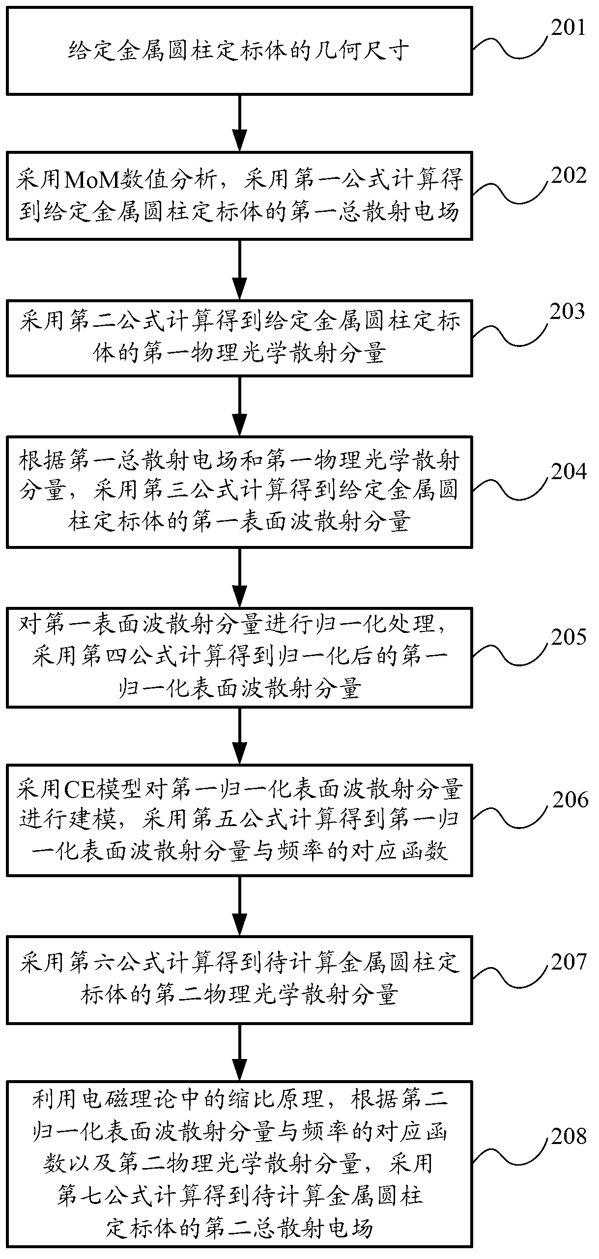
The invention provides a method for calculating a radar scattering cross section of a metal cylindrical calibration body, which comprises the following steps of: pre-setting the size of the metal cylindrical calibration body; calculating a first total scattering electric field of the pre-set metal cylindrical calibration body by adopting MoM numerical value analysis; obtaining a first physical optical scattering component of the pre-set metal cylindrical calibration body by utilizing a PO formula; calculating a first surface wave scattering component of the pre-set metal cylindrical calibration body according to the first total scattering electric field and the first physical optical scattering component, and carrying out normalization processing of the first surface wave scattering component to obtain a first normalized surface wave scattering component; modelling the first normalized surface wave scattering component by adopting a CE model to obtain corresponding functions of the first normalized surface wave scattering component and frequency; obtaining a second physical optical scattering component of the metal cylindrical calibration body to be calculated by utilizing the PO formula; and calculating to obtain a second total scattering electric field of the metal cylindrical calibration body to be calculated by utilizing the shrinkage ratio principle according to the corresponding functions and the second physical optical scattering component.

Description

technical field [0001] The invention relates to radar signal processing technology, in particular to a method for calculating the radar scattering cross section of a metal cylinder calibration body. Background technique [0002] The target radar cross section (Radar Cross Section, hereinafter referred to as: RCS) measurement generally adopts the relative calibration measurement method, that is, the target to be measured and a calibration object that can accurately calculate the theoretical total scattering electric field are measured separately, through two radar returns The ratio of the wave signal, the measured value of the target RCS is obtained from the known total scattered electric field of the calibration body. Since the received echo power of the calibration body and the target to be measured all satisfy the radar equation [0003] P r = P t ...

Claims


Application Information

Patent Timeline
Patent Type & Authority Applications(China)
IPC IPC(8): G01S7/41
Inventor 许小剑贺飞扬谢志杰
Owner BEIHANG UNIV
Learn More