
Hinge joint positioning device for tube

The technology of positioning device and leg tube is applied in the field of furniture accessories, which can solve the problems of easy hand clamping, potential safety hazards, and many consumables, etc., and achieve the effects of convenient operation and simple structure.

Inactive Publication Date: 2015-06-17
郑雪峰
View PDF6 Cites 0 Cited by
  • Summary
  • Abstract
  • Description
  • Claims
  • Application Information

AI Technical Summary

Problems solved by technology

[0002] At present, the hinged positioning structure of the leg tube of common furniture is usually supported by a support hinge, which is composed of two pieces of metal. This support hinge has a shear point, which is easy to pinch hands during use, posing a safety hazard; there are also some furniture. The support tube is used for positioning and connection. This structure requires separate disassembly and fixed installation of the support tube during use, resulting in cumbersome operation and a lot of consumables.

Method used


Image

  • Hinge joint positioning device for tube
  • Hinge joint positioning device for tube
  • Hinge joint positioning device for tube

Examples


Embodiment

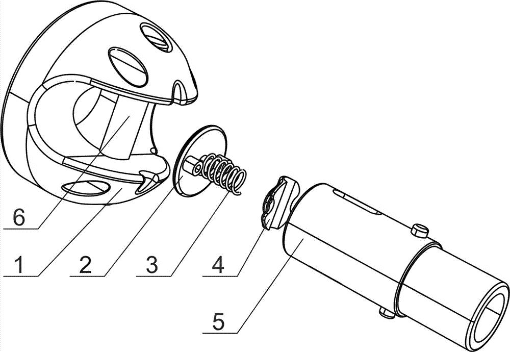
[0019] Example: refer to figure 1 , a hinged positioning device for a foot tube, which includes a fixed seat 1, an end cover 2, a spring 3, a slider 4, a hinged seat 5, and a rivet 6; the feature is that the spring 3 is arranged between the end cover 2 and the slider 4 , the end cover 2 is fixed on the hinged seat 5, the slider 4 is arranged in the hinged seat 5, and the hinged seat 5 is hinged with the fixed seat 1 through the rivet 6.

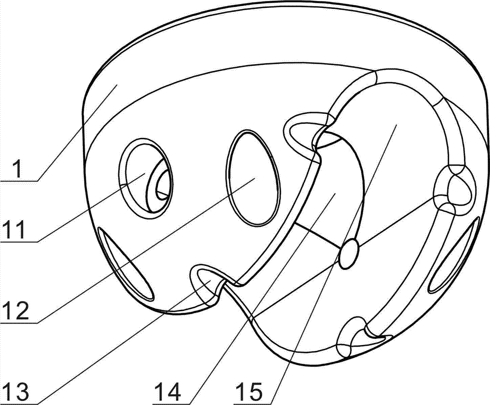
[0020] refer to figure 2 , the fixed seat 1 is provided with a hinged hole 11, a positioning hole 12, a positioning gap 13, a positioning groove 14, and a limit wall 15; The shape of the hinged seat 5 matches.

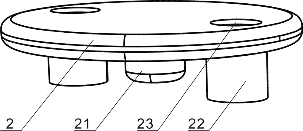
[0021] refer to image 3 , the end cover 2 is provided with a positioning post 21, a boss post 22, and a screw hole 23; a spring 3 is installed on the positioning post 21 to guide and support the spring 3;

[0022] refer to Figure 4 , the slider 4 is provided with a guide groove 41, a plane boss 42, and a groove 43; the guide ...


PUM


Abstract

The invention relates to a hinge joint positioning device for a tube, and the hinge joint positioning device comprises a fixed base, an end cap, a spring, a sliding block, a hinge joint base and rivets. The hinge joint positioning device for the tube is characterized in that the spring is arranged between the sliding block and the end cap, the end cap is fixedly connected to the hinge joint base, the hinge joint base is hinged with the fixed base by virtue of the rivets, positioning support of the hinge joint base can be realized only requiring that the hinge joint base is arranged in a positioning slot on the fixed base; and when rotating and folding are required, the hinge joint base is pulled only, so that the rivets push the sliding block to compress the spring, the spring is compressed and shortened, the hinge joint base is separated from the positioning slot, and free rotating of the hinge joint base can be realized. Thus, the hinge joint positioning device for the tube provided by the invention has the advantages of simple structure, easiness operation and suitability for being used as an accessory for furniture.

Description

technical field [0001] The invention relates to a furniture accessory, in particular to a hinged positioning device for a leg tube. Background technique [0002] At present, the hinged positioning structure of the leg tube of common furniture is usually supported by a support hinge, which is composed of two pieces of metal. This support hinge has a shear point, which is easy to pinch hands during use, posing a safety hazard; there are also some furniture. The positioning and connection of the support tube is adopted. During the use of this structure, the support tube needs to be disassembled and fixed separately, resulting in a cumbersome operation process and a lot of consumables. Contents of the invention [0003] In order to overcome the deficiencies of the prior art, the invention provides a hinged positioning device for the leg tube, which can simplify the structure, facilitate operation and eliminate potential safety hazards. [0004] The technical solution adopted ...

Claims


Application Information

Patent Timeline
Patent Type & Authority Patents(China)
IPC IPC(8): F16C11/10F16C11/12
Inventor 郑雪峰
Owner 郑雪峰
Learn More