Fork shrinkage type screw jack

A jack and screw technology, applied in the direction of the lifting device, etc., can solve the problems of bending deformation, danger, failure and other problems of the jack, and achieve the effects of simplified processing, better structure and manufacturability, and reduced cost

Inactive Publication Date: 2013-04-03
NANTONG TONGRUN AUTO ACCESSORY
View PDF9 Cites 3 Cited by
  • Summary
  • Abstract
  • Description
  • Claims
  • Application Information

AI Technical Summary

Problems solved by technology

Figure 12 The shown hinge shaft connection process is cumbersome, Figure 11 The hinge shaft shown is easy to connect and install, but after installing the shaft head of the hinge block or hinge nut, the opening of the "U" groove on the support arm must be closed to prevent the hinge block or hinge nut from shedding
Also because of this, the reliability of the opening of some "U" shaped slots is not perfect after forming a rotating pair between the paired upper support arms and the paired lower support arms. , after being subjected to an external force, it may cause the upper support arm and the lower support arm to separate from the opening of the "U"-shaped groove, causing the fork retractable screw jack to disintegrate and fail; The jacking position of a small platform top-loading supporting vehicle is either a simple inverted "U"-shaped frame bent into two right angles as the top structure. Although it is easy to process, after a little use, it often appears The overall failure or even danger of the jack caused by bending deformation

Method used


Image

  • Fork shrinkage type screw jack
  • Fork shrinkage type screw jack
  • Fork shrinkage type screw jack

Examples


Embodiment Construction

[0025] The following will further describe the present invention in conjunction with the accompanying drawings of the embodiment, which will help the public to understand the technical content and effect of the case, but the description of the embodiment does not constitute a limitation to the technical solution. Any transformation that is merely equivalent in form should be regarded as the scope of the technical solution of this case.

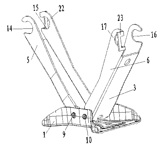
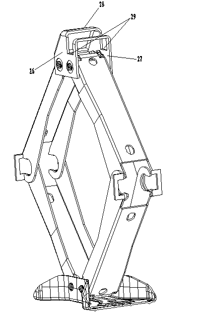
[0026] As can be seen from the accompanying drawings, the embodiment of the present invention is based on the traditional scissor jack, and optimizes the design of each mechanical structure. The paired lower support arm groups 3 are connected with the base 1, and the paired upper support arm groups 4 is connected with the head 2. The first lower supporting arm 5 and the second lower supporting arm 6 are arranged in the lower supporting arm group 3, and the first upper supporting arm 7 and the second upper supporting arm 8 are arranged in the u...


PUM


Abstract

The invention discloses a fork shrinkage type screw jack, comprising a lower supporting arm group and an upper supporting arm group, wherein each upper supporting arm and each lower supporting arm have similar geometry elements and are provided with the same U-shaped open slot and reinforcing framework respectively; an included angle of 126+ / -5 degrees is formed between a symmetry plane of each U-shaped open slot formed by the upper supporting arm and the lower supporting arm and a ligature reference plane between the center lines of rotary shaft holes; a first side plate, a second plate, a reinforcing inclined plate, a clamping slot, a closed frame and a top plate are formed on an ejector header; and respective rotation pairs of the lower supporting arm group and the upper supporting arm group are formed through the rotation connection of a hinge block and a hinge nut at each U-shaped open slot. The fork shrinkage type screw jack has the beneficial effects that as each part and relevant structure elements are optimized, each rotation pair is enabled to be more reliable and have more excellent structure technological performance; and the reinforced ejector header structure causes a vehicle to be jacked more safely.

Description

technical field [0001] The invention belongs to lifting machinery tools used in vehicle maintenance, and in particular relates to a retractable screw jack tool. Background technique [0002] The more typical scissor jack among mechanical lifting tools is actually a kind of fork retractable screw jack. Combination of bearings, screw rods, stop positioning sleeves, etc. Traditional telescopic screw jacks generally have a pair of upper support arms and a pair of lower support arms. Figure 12 The closed full-circle pin hole in the prior art shown combines the two ends of the hinge block and the two ends of the hinge nut to form the revolving pair at the hinge block and the revolving pair at the hinge nut, and the above-mentioned Figure 12 The closed full-circle pin holes shown are modified in some designs to: center pin holes at one end of each support arm to hinge blocks (or center pin holes to hinge nuts at the other end of each support arm) Make a "U"-shaped opening slot o...

Claims


Application Information

Patent Timeline
IPC IPC(8): B66F3/08
Inventor 盛永明顾晓峰陈有源林来顺
Owner NANTONG TONGRUN AUTO ACCESSORY
Why Eureka
Try Eureka