
A combined die

A combined die technology, applied in the field of combined dies, can solve problems such as die hole deformation, die waste, and increase production costs, and achieve the effects of avoiding unsmooth production, reducing production costs, and avoiding waste

Active Publication Date: 2016-02-10
KINGFA SCI & TECH CO LTD +1
View PDF5 Cites 0 Cited by
  • Summary
  • Abstract
  • Description
  • Claims
  • Application Information

AI Technical Summary

Problems solved by technology

When the die is used for a period of time, the die hole in the die will be deformed, and the entire die must be replaced
Otherwise, the die after the die hole deformation will seriously affect the appearance quality of plastic particles, and will also cause unsmooth production
Since the entire die has to be replaced only because of the deformation of the die holes in the die, this will greatly increase the production cost
And sometimes only one or two of the multiple die holes in the entire die is deformed, and most of the die holes can still be used normally, but the entire die must be replaced, so this will be a very large die waste

Method used


Image

  • A combined die
  • A combined die
  • A combined die

Examples


Embodiment 1

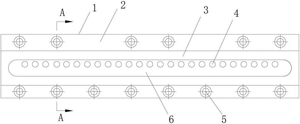
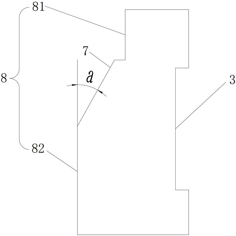
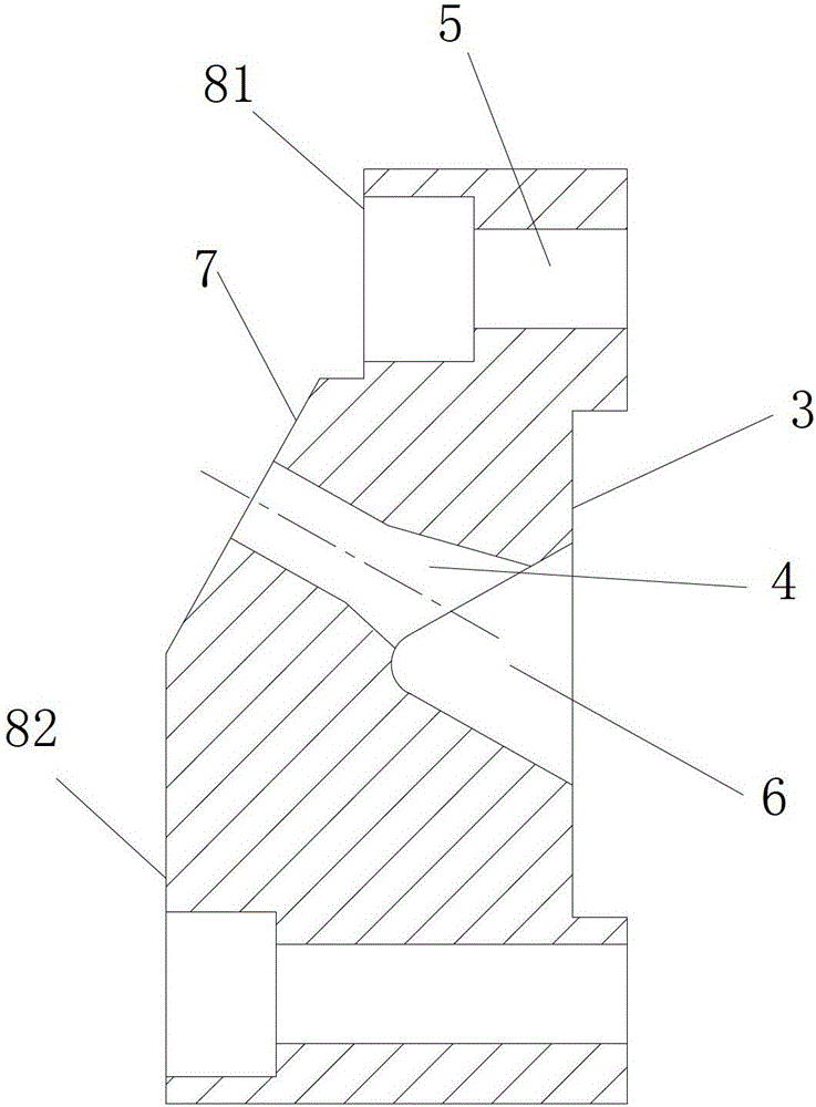
[0023] like Figure 1 to Figure 4 A combined die shown includes a die main body 1, the feed side end face 2 of the die die main body 1 is connected to the extruder head, and the feed side end face 2 is provided with a connecting groove 3, the A through hole 4 is provided at the bottom of the connecting groove 3 , and a die hole liner 9 matching the size of the through hole 4 is fixedly installed in the through hole 4 . The combined die of this embodiment is applied to a twin-screw extruder.

[0024] As a preference, the die hole liner 9 is fixedly installed in the through hole 4 through interference fit. The fixed installation method of interference fit can facilitate the installation or removal of the die hole liner 9 .

[0025] As a preference, the die hole liner 9 includes a cylindrical ejection section 91 and a trumpet-shaped feed section 92, and the die hole diameter of the feed section 92 is greater than the die hole diameter of the ejection section 91, and The feedin...

Embodiment 2

[0035] This combined die is the same as embodiment 1 except the following features: the size of the included angle a is 45°.

Embodiment 3

[0037] This combined die is the same as embodiment 1 except the following features: the size of the included angle a is 75°.


PUM


Abstract

The invention discloses a combined die, comprising a die main body, wherein the end face of the feeding side of the die main body is connected with an extruder head; a connection groove is formed in the end face of the feeding side of the die main body; a through hole is formed at the bottom of the connection groove; and a die hole liner correspondingly matched with the through hole in size is fixedly mounted inside the through hole. When the die hole liner provided by the invention is deformed, the deformed die hole liner only needs to be replaced, and the entire die does not need of to be replaced, therefore, the production cost can be reduced, and the die can be prevented from being wasted.

Description

technical field [0001] The invention relates to mold equipment, in particular to a combined die. Background technique [0002] The die is a key process equipment for the production of products in the modified plastics industry. Its main function is to shape the molten material in the twin-screw extruder. The molten material will form a strip material after passing through the die, and the strip material will enter the subsequent auxiliary equipment of the production line to form plastic particles. [0003] At present, in the production of modified plastic products, the die used in the factory is an integrated die. After the die is used for a period of time, the die hole in the die will be deformed, and the whole die must be replaced. Otherwise, the die after the deformation of the die hole will seriously affect the appearance quality of the plastic particles, and at the same time, it will cause the production to be unsmooth. Since the entire die has to be replaced only b...

Claims


Application Information

Patent Timeline
Patent Type & Authority Patents(China)
IPC IPC(8): B29C47/12B29C48/30
Inventor 罗李波钱永红袁绍彦王大中叶南飚刘奇祥吴博
Owner KINGFA SCI & TECH CO LTD
Learn More