
Air cooling mechanism for screw rod

An air-cooled, screw-screw technology, used in metal processing machinery parts, maintenance and safety accessories, metal processing equipment, etc., can solve the high cost of equipment maintenance and repair, the difficulty of screw manufacturing and processing, and the increase of equipment costs, etc. problems, to achieve the effect of high maintenance and repair costs in the later stage, reducing production costs and reducing manufacturing difficulty.

Inactive Publication Date: 2014-12-17
HANGZHOU SANTUO PRECISION MACHINERY
View PDF8 Cites 0 Cited by
  • Summary
  • Abstract
  • Description
  • Claims
  • Application Information

AI Technical Summary

Problems solved by technology

[0003] 1. There are special requirements for the screw rod itself. It is required that the screw rod has a hollow structure so that the cooling oil can flow in the screw rod to take away the heat generated by the screw rod due to friction. However, the manufacturing and Processing is very difficult, which increases the cost of equipment
[0004] 2. Since the screw is in a high-speed rotating state during the operation of the machine tool, under normal circumstances, the speed of the screw is above 3000 rpm. In order to ensure that there is no leakage when the cooling oil enters and exits the screw, a screw is required There is a good sealing performance between the docking mechanism and the docking mechanism, which greatly increases the complexity of the equipment and increases the cost of the equipment
[0005] 3. When using cooling oil to cool the screw rod, after the machine tool has been working for a period of time, there will usually be leakage of cooling oil, resulting in high maintenance and repair costs for the equipment. Once the equipment fails, it will bring production stagnation
[0006] 4. The cooling oil flows in the screw rod of the hollow structure to take away the heat generated by the friction of the screw rod, that is, the cooling oil cools the screw rod from the inside to the outside, but the screw rod is in the working process Among them, the heat generated by friction is generated from the surface of the screw, that is to say, the thermal deformation on the screw is from the outside to the inside, which makes it difficult for the heat generated by the friction of the screw to be cooled by the oil in a timely and effective manner. Take away, the effect of heat transfer is poor, the control of the thermal deformation of the screw is affected, and ultimately the accuracy of the screw is affected
[0007] 5. The operation of the oil cooling mechanism requires special cooling oil, and the oil needs to be replaced regularly, resulting in a waste of resources, and then it also brings problems such as waste oil recycling
[0008] 6. A set of independent refrigeration mechanism and pressure conveying mechanism need to be added to the machine tool, which increases the manufacturing cost of the equipment and leads to an increase in the purchase cost of the enterprise. At the same time, the later maintenance and use costs of the equipment also increase accordingly
[0010] In summary, there is no screw cooling mechanism with simple structure, reasonable design, low manufacturing cost, and good cooling effect on the screw rod.

Method used


Image

  • Air cooling mechanism for screw rod
  • Air cooling mechanism for screw rod
  • Air cooling mechanism for screw rod

Examples


Embodiment Construction

[0037] The present invention will be further described in detail below with reference to the accompanying drawings and through embodiments.

[0038] Example.

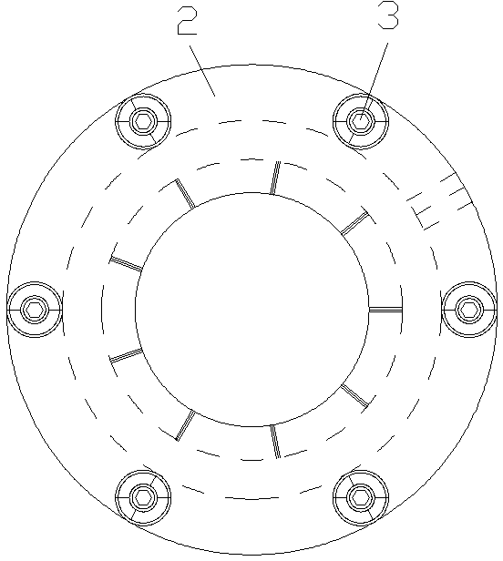
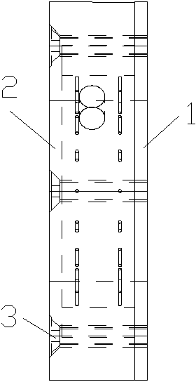
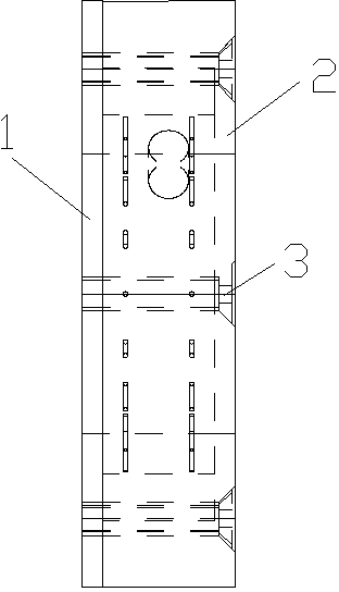
[0039] see Figure 1 to Figure 16 , the screw air cooling mechanism in this embodiment is composed of an inner ring 1, an outer ring 2 and six screws 3. The number of screws 3 in the present invention can be set according to actual needs, and the number of screws 3 is generally three above.

[0040] The inner ring 1 is composed of an inner ring body 11 and an air cooling jacket 12. The inner ring body 11 is a circular ring structure, and an inner ring circular hole 15 is arranged in the center of the inner ring body 11. There are the same number of inner ring connecting holes 14 as screws. A sealing ring 17 is arranged around the inner ring body 11 .

[0041]The air-cooling jacket 12 has a cylindrical structure, and the air-cooling jacket 12 is provided with a screw channel 16, the screw channel 16 is a cylindrical ...


PUM


Abstract

The invention relates to an air cooling mechanism for a screw rod, and is mainly used in a high-precision machine tool. No cooling mechanism which has a simple structure and a good cooling effect on the screw rod exists currently. The air cooling mechanism for the screw rod is characterized by consisting of an inner ring, an outer ring and a plurality of screws, wherein the inner ring consists of an inner ring body and an air cooling sleeve, an inner ring circular hole is arranged in the inner ring body, a screw rod channel is arranged in the air cooling sleeve, a wall surface of the air cooling sleeve is uniformly provided with two circles of air outlet holes, and axes of the air outlet holes are all vertically intersected with the axis of the air cooling sleeve; and the air cooling sleeve is fixed on the inner ring body, the outer ring consists of an outer ring body and an outer ring loop, an outer ring circular hole is arranged in the outer ring body, a wall surface of the outer ring loop is provided with an air inlet, the inner ring and the outer ring are fixed through the plurality of screws, the screw rod channel is aligned to the outer ring circular hole, and the inner ring body, the air cooling sleeve, the outer ring body and the outer ring loop define a cooled air distribution cavity in an annular structure. The air cooling mechanism has a simple structure, is low in manufacturing cost, and has a good cooling effect on the screw rod.

Description

technical field [0001] The invention relates to an air-cooling mechanism, in particular to an air-cooling mechanism for a screw rod, which is mainly used in high-precision machine tools for cooling the screw rod. Background technique [0002] When the machine tool is running, heat is generated between the lead screw and the nut seat on the machine tool due to friction, and this heat will cause thermal expansion of the lead screw, thereby affecting the accuracy of the lead screw. At present, the commonly used machine tools usually use oil cooling to deal with the thermal expansion of the screw, that is, the screw is made into a hollow structure, and the cooling oil used for cooling can flow in the screw of the hollow structure. The oil cooling method mainly has the following shortcomings. [0003] 1. There are special requirements for the screw itself, requiring the screw to be a hollow structure, so that the cooling oil can flow in the screw to take away the heat generated ...

Claims


Application Information

Patent Timeline
Patent Type & Authority Patents(China)
IPC IPC(8): B23Q5/40B23Q11/12
Inventor 高飞烽喻艳
Owner HANGZHOU SANTUO PRECISION MACHINERY
Learn More