
Biological environment-friendly expansion-drop combination energy dissipater

An eco-environment-friendly technology, applied in water conservancy projects, sea area projects, coastline protection, etc., can solve the problems that the bottom plate is threatened by the vertical shaft vortex, shorten the length of the stilling pool, etc., to improve the downstream ecological environment, the atomization range is small, Reduce the effect of twirling

Active Publication Date: 2013-03-13
CHINA THREE GORGES CORPORATION
View PDF9 Cites 16 Cited by
  • Summary
  • Abstract
  • Description
  • Claims
  • Application Information

AI Technical Summary

Benefits of technology

This patented technology relieves environmental concerns from current methods that use litter or sediment. It uses an eco -friendly droplet expansion type combination energy disselerating apparatus called this patent's solution. By changing its shape during operation, the equipment becomes more efficient at reducing fluid velocity while also being less affected by any other factors like pressure fluctuations. Additionally, there are technical advantages over previous designs where they were designed without causing damage to the underlying aquatic area. Overall, these improvements enhance the performance of the overall system.

Problems solved by technology

This technical problem addressed in this patented text relates to the issue of gas condupletion during hydroplanckoning processes where the movement of liquid molecules causes deteriorating levels in the vicinity of the lower part of the vessel called the sea floor. Gas accumulations occur due to rapid changes in density and direction caused by fluid movements around them. These issues lead to potential harmful effects like corrosion and instability of equipment structures. Current solutions involve adding extra layers of material to prevent these negative influences but their effectiveness remains unclear even though some improvements exist.

Method used


Image

  • Biological environment-friendly expansion-drop combination energy dissipater
  • Biological environment-friendly expansion-drop combination energy dissipater
  • Biological environment-friendly expansion-drop combination energy dissipater

Examples


Embodiment 1

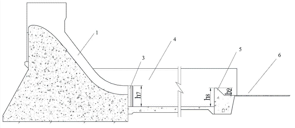
[0044] The structure of the eco-environmentally friendly drop-expansion combined energy dissipator in this embodiment is as follows: figure 1 , figure 2 , Figure 5 , Figure 9 , Figure 11 and Figure 13 As shown, its structural composition includes seven high sill discharge troughs 1, seven low sill sill discharge troughs 2, solid water carrying sills 10, seven chute partition walls 7, stilling pools 4, and stilling pool tail sills 5 , Downstream apron 6. It should be noted that the number of the above-mentioned high sill drain grooves and low sill drain grooves is only exemplary, and should not be construed as limiting, and the number can be two, three or any number.

[0045] Among them: the high sill discharge tank 1 is a non-pressurized horizontal outflow in the form of splits, such as Figure 5 shown; each drain slot 1 width d 2 =12m, the thickness of the chute partition wall is 7 d 3 =4m. The low-sill discharge trough and the high-sill discharge trough are arr...

Embodiment 2

[0047] The structure of the eco-environmentally friendly drop-expansion combined energy dissipator in this embodiment is as follows: figure 1 , figure 2 , Figure 6 , Figure 9 , Figure 11 and Figure 13 As shown, the structural composition includes seven high sill discharge troughs 1, seven low sill sill discharge troughs 2, solid water carrying sills 10, seven chute partition walls 7, stilling pools 4, stilling pool tail sills 5, Downstream armor 6. Among them: the high-sill discharge trough is in the form of splits without pressure outflow, and the outlet of the high-sill discharge trough is set at a depression angle of 1:10 from the end of the overflow dam surface, as shown in Figure 6 Shown; each high sill 1 width d 2 =12m, the thickness of the chute partition wall is 7 d 3 =4m, 1:10 depression angle section 9 length L 6 =8m. The low-sill discharge trough and the high-sill discharge trough are arranged in parallel in the same way, and they are pressurized mult...

Embodiment 3

[0049] The structure of the eco-environment friendly drop-diffusion bottom flow energy dissipator in this embodiment is as follows: figure 1 , figure 2 , Figure 5 , Figure 10 , Figure 11 , Figure 14 and Figure 15 As shown, the structural composition includes seven high sill discharge troughs 1, seven low sill sill discharge troughs 2, tooth grid type water carrying sills 11, seven chute partition walls 7, stilling pool 4, and stilling pool tail sill 5 , Downstream apron 6. Among them: the high sill discharge trough is a non-pressurized horizontal outflow in the form of splits, such as Figure 5 Shown; each high sill 1 width d 2 =12m, the thickness of the chute partition wall is 7 d 3 =4m. The low sill discharge trough 2 and the high sill discharge trough 1 are arranged in parallel in the same arrangement, both of which are pressurized and multi-strand outflows, such as Figure 10 As shown, each low sill chute is 2 wide d 1 =12m, the thickness of the chute part...


PUM


Abstract

The invention belongs to a flood discharge energy dissipation facility, and discloses a biological environment-friendly expansion-drop combination energy dissipater. The energy dissipater comprises a plurality of upstream flood discharge slots, flood discharge partition walls arranged among the upstream flood discharge slots, a flow picking structure arranged at the tail ends of the upstream flood discharge slots, a stilling basin arranged at the downstream of the flow picking structure, and a stilling basin tail weir and a downstream apron arranged at the downstream of the stilling basin, wherein the upstream flood discharging slots consist of a plurality of high-weir flood discharge slots and a plurality of low-weir flood discharge slots; and the high-weir flood discharge slots and the low-weir flood discharge slots are arranged in parallel from top to bottom. According to energy dissipater provided by the invention, the problem that the bottom plate of multi-strand flood discharge downstream stilling basin is suffered from the threat of vertical vortex under large flow; and moreover, under the promise that the energy dissipation efficiency of the bottom flow energy dissipater is improved, the gas super-saturation is reduced, and the influence to the downstream biological environment is reduced.

Description


Claims


Application Information

Patent Timeline
Owner CHINA THREE GORGES CORPORATION
Learn More