Lock cylinder structure

A lock core and core body technology, applied in architectural locks, cylinder marble locks, building structures, etc., can solve the problems of poor anti-pick performance and low security, and achieve the effect of high security and good anti-pry performance.

Active Publication Date: 2015-04-22
吴正华
View PDF7 Cites 0 Cited by
  • Summary
  • Abstract
  • Description
  • Claims
  • Application Information

AI Technical Summary

Problems solved by technology

[0003] In order to overcome the disadvantages of poor tamper-proof performance and low security of the existing lock cylinder structure, the present invention provides a lock cylinder structure with good tamper-proof performance and high safety

Method used


Image

  • Lock cylinder structure

Examples


Embodiment Construction

[0008] The present invention will be further described below in conjunction with the drawings.

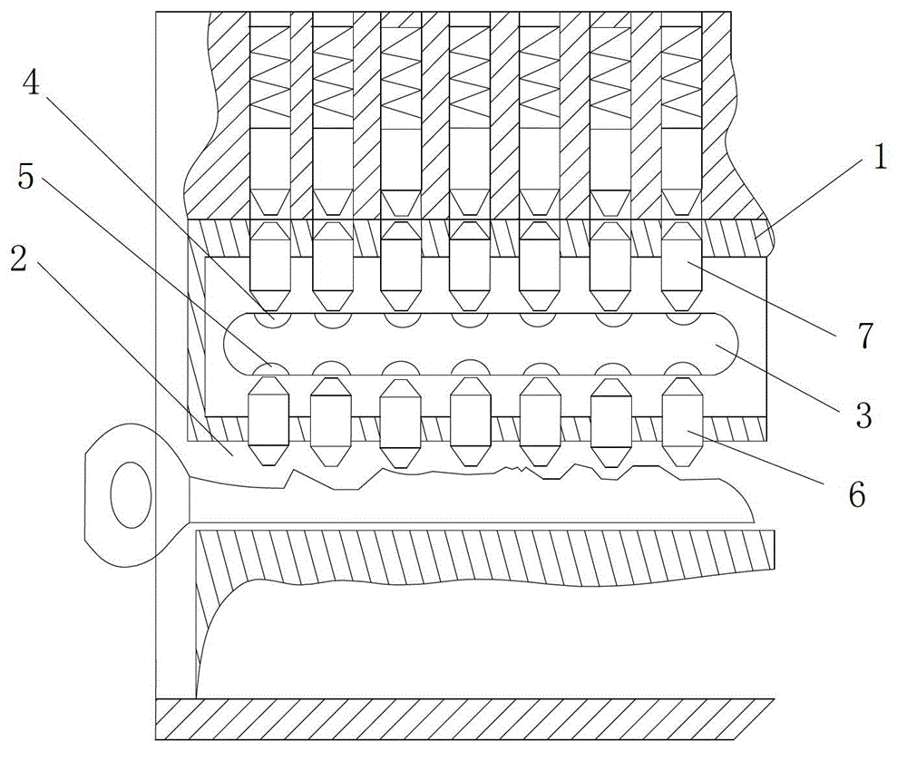
[0009] Reference figure 1 , A lock core structure, comprising a core body 1, a key hole 2 for inserting a key is provided in the core body 1, a cavity is opened in the core body 1, and a linkage plate 3 is provided in the cavity. The upper ends of the linkage plates 3 are respectively provided with upper positioning grooves 4 along the keyhole direction, the lower ends of the linkage plates are respectively provided with lower positioning grooves 5 along the keyhole direction, and the cores above the linkage plates are arranged radially in sequence The upper pin hole, the lower pin hole is arranged radially in the core below the linkage piece, the lower pin 6 is located in the lower pin hole, the upper end of the lower pin 6 is in the lower positioning groove 5, and the upper pin 7 is located in the upper pin hole, the lower end of the upper pin 7 is in the upper positioning groove 4...


PUM


Abstract

The invention discloses a lock cylinder structure which comprises a lock cylinder body; a keyhole for inserting a key is arranged in the lock cylinder body; a hollow cavity is arranged in the lock cylinder body; a linkage plate is arranged in the hollow cavity; upper positioning slots are respectively arranged at the upper end of the linkage plate along the direction of the keyhole, and lower positioning slots are respectively arranged at the lower end of the linkage plate along the direction of the keyhole; upper billiard holes are sequentially distributed in the radial direction in the lock cylinder body above the linkage plate, and lower billiard holes are sequentially distributed in the radial direction in the lock cylinder body below the linkage plate; lower billiards are located in the lower billiard holes, with the upper ends propping in the lower positioning slots; upper billiards are located in the upper billiard holes, with the lower ends propping in the upper positioning slots; and the upper ends of the upper billiards match with lock body billiards. The lock cylinder structure provided by the invention has good anti-prising performance and high safety.

Description

Technical field [0001] The invention relates to a lock core structure. Background technique [0002] The existing lock cylinder includes a core body, the core body is provided with a key hole for a key to be inserted, and a pin hole is arranged radially in the core body along the key hole direction, and the lock cylinder pin is slidably installed in the pin hole up and down The lock cylinder is rotatably sleeved on the lock body, the lock body is provided with a lock body pin slot, the bottom of the pin slot is installed with a spring, the spring is pressed against the lock body pin, the lock body pin Match with the lock cylinder pin; when the key is inserted into the key hole, each lock cylinder pin is matched with the lock body pin, and the contact part of each lock cylinder pin and the lock body pin is just the contact surface between the lock body and the lock cylinder It can realize normal unlocking; the existing technical defects are: the use of unlocking tools to move the...

Claims


Application Information

Patent Timeline
Patent Type & Authority Patents(China)
IPC IPC(8): E05B27/00E05B17/20
Inventor 吴正华
Owner 吴正华
Why Eureka
Try Eureka