
Car camera out/in device

A camera and vehicle-mounted technology, applied in optical observation devices, vehicle components, transportation and packaging, etc., can solve the problems of interfering with the moving path of the camera 1, interference, etc., and achieve the effect of reducing weight, saving costs, and ensuring the moving path.

Active Publication Date: 2016-12-21
HYUNDAI MOBIS CO LTD
View PDF5 Cites 0 Cited by
  • Summary
  • Abstract
  • Description
  • Claims
  • Application Information

AI Technical Summary

Problems solved by technology

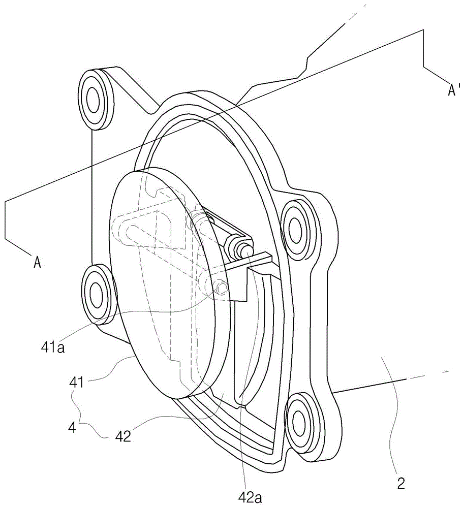
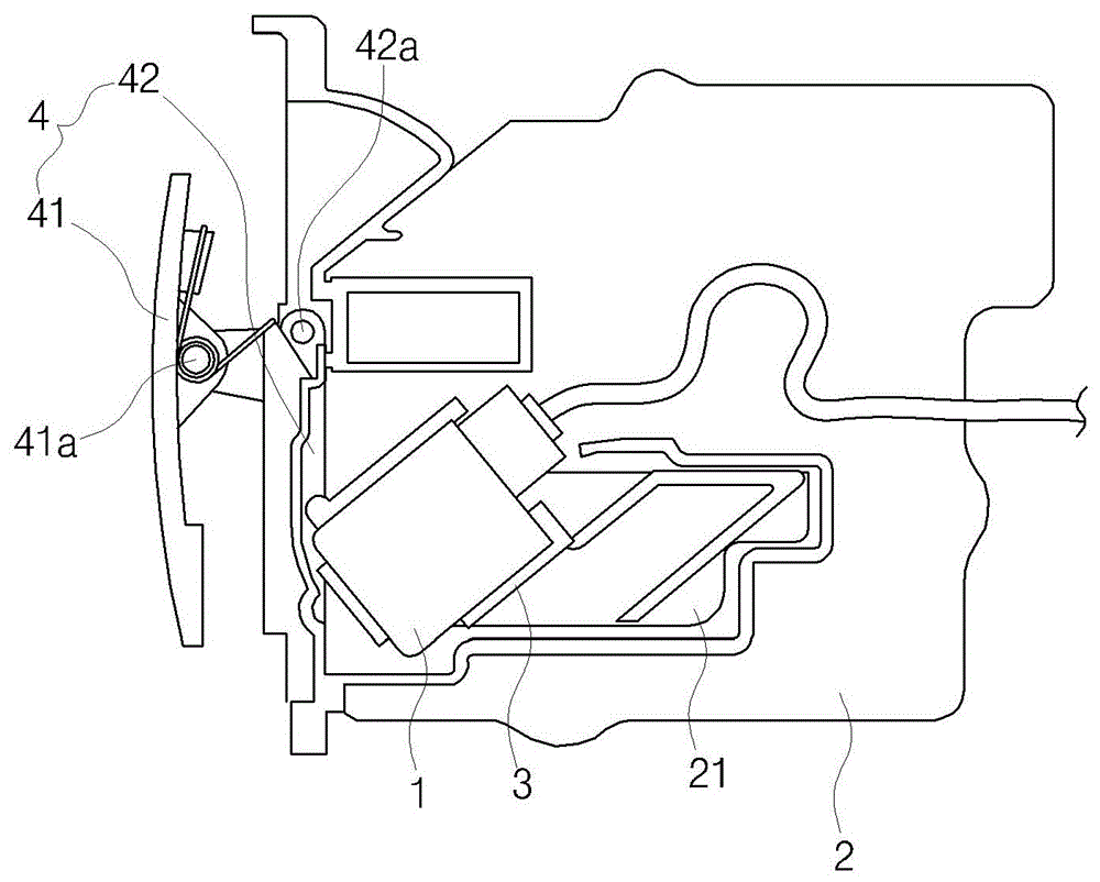
[0014] However, when the inner cover 42 and the outer cover 41 are opened or closed at the same time, in order to rotate the shafts 42a, 41a respectively provided by the inner cover 42 and the outer cover 41, during the process that the camera 1 protrudes outside the bracket 1 to sense the image outside the vehicle, the inner cover The shaft 42a and the housing shaft 41a interfere with the movement path of the camera 1
In addition, when the moving path of the camera 1 moves vertically from the cover assembly 4, interference occurs between the camera 1 and the inner cover axis 42a or the outer cover axis 41a.

Method used


Image

  • Car camera out/in device
  • Car camera out/in device
  • Car camera out/in device

Examples


Embodiment Construction

[0033] The specific implementation manner of the present invention will be described in detail below in conjunction with the accompanying drawings. First, when attaching reference symbols to constituent elements of drawings, the same symbols are used as much as possible for the same constituent elements even if they are marked on different drawings. In addition, when introducing the present invention, specific descriptions related to known structures or functions may obscure the gist of the present invention, and specific descriptions are omitted.

[0034] In addition, the same configurations as those described in the conventional art described above are assigned the same reference numerals, and a detailed description thereof will be omitted.

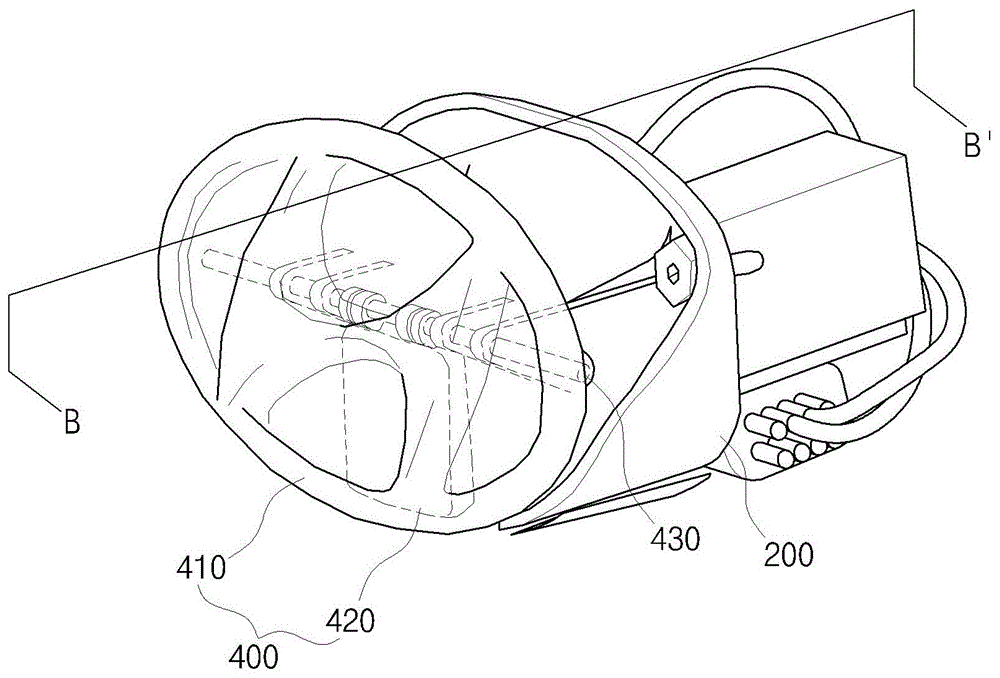
[0035] image 3 It is an oblique view of a vehicle-mounted camera output / receiving device related to a specific embodiment of the present invention, Figure 4 for along image 3 Sectional view of the BB' cut shown.

[0036] Such as ...


PUM


Abstract

PURPOSE: A device for pulling a camera in and out for a vehicle is provided to secure a moving path for the camera, reduce costs, and have a reduced size. CONSTITUTION: A device for pulling a camera in and out for a vehicle comprises a frame(200), a moving member(300), and a cover assembly(400). The frame includes a moving passage where a camera(100) is pulled in and out through an open end portion of one side of the frame. The moving member moves while moving the camera. The cover assembly includes an outer cover(410) which is exposed to the outside of a vehicle and an inner cover(420) which is arranged in the rear surface of the outer cover and opens and closes the open end portion of the frame.

Description

technical field [0001] The invention relates to a vehicle-mounted camera receiving / receiving device. Specifically, the sign on the rear of the car and the shaft of the inner cover are integrated, and the moving path of the camera is changed to face downward to ensure the moving path of the camera. Background technique [0002] Most recent cars on the market are equipped with surveillance cameras that monitor the state of the car's exterior, or for obstacles behind it when reversing. [0003] This kind of camera needs to monitor the external position of the appearance of the car body, and forms a groove that can be used to install and fix the camera, so that the camera protrudes to the outside of the groove, so as to monitor the state of the outside of the car. [0004] At this time, when the camera sticks out directly, it is easy for foreign matter to enter and it is also easy to be damaged, so the cover assembly is installed for the purpose of protecting the camera when it ...

Claims


Application Information

Patent Timeline
Patent Type & Authority Patents(China)
IPC IPC(8): B60R11/04
CPCB60R1/00B60R11/04B60R13/005B60R2300/8066
Inventor 曺永炅
Owner HYUNDAI MOBIS CO LTD
Learn More