Display and line sorting structure thereof

A wire management structure and wire management technology, which is applied in the direction of instruments, electrical digital data processing, digital data processing parts, etc., can solve the problems of wire management buckle jumping out of the shaft hole, high design difficulty, etc., and achieve the effect of improving reliability

Active Publication Date: 2013-02-20
QISDA SUZHOU +1
View PDF6 Cites 2 Cited by
  • Summary
  • Abstract
  • Description
  • Claims
  • Application Information

AI Technical Summary

Problems solved by technology

[0002] In order to meet the requirements of end users for the appearance of display devices such as LCD monitors and LCD TVs, the customization of complete machine products has become the mainstream. However, in pursuit of light, thin, short and multiple appearances, the internal structure design must be coordinated with changes to strengthen the structure. Load the weight of the whole product and the external force acting on it. Therefore, under the consideration of product cost and functionality, the design difficulty is getting higher and higher, so that the manufacturing process must be relatively improved to meet the diversified design requirements.
[0003] The line management structure in the current known technology has such Figure 1 to Figure 3 In the structure shown, the display has a cable management buckle 40, and the cable management buckle 40 is combined with the support member 30 of the display by using the shaft hole 36, so that the shaft part 42 of the cable management buckle 40 is fitted into the shaft hole 36 to achieve a rotational movement; but The cable management buckle 40 is within the range of the rotation track, and its rotating arm may be caused by external force (manufacturing, transportation, drop test, etc.), causing the cable management buckle to jump off the shaft hole

Method used


Image

  • Display and line sorting structure thereof
  • Display and line sorting structure thereof
  • Display and line sorting structure thereof

Examples


Embodiment Construction

[0028] In order to have a further understanding of the purpose, structure, features, and functions of the present invention, the following detailed descriptions are provided in conjunction with the embodiments.

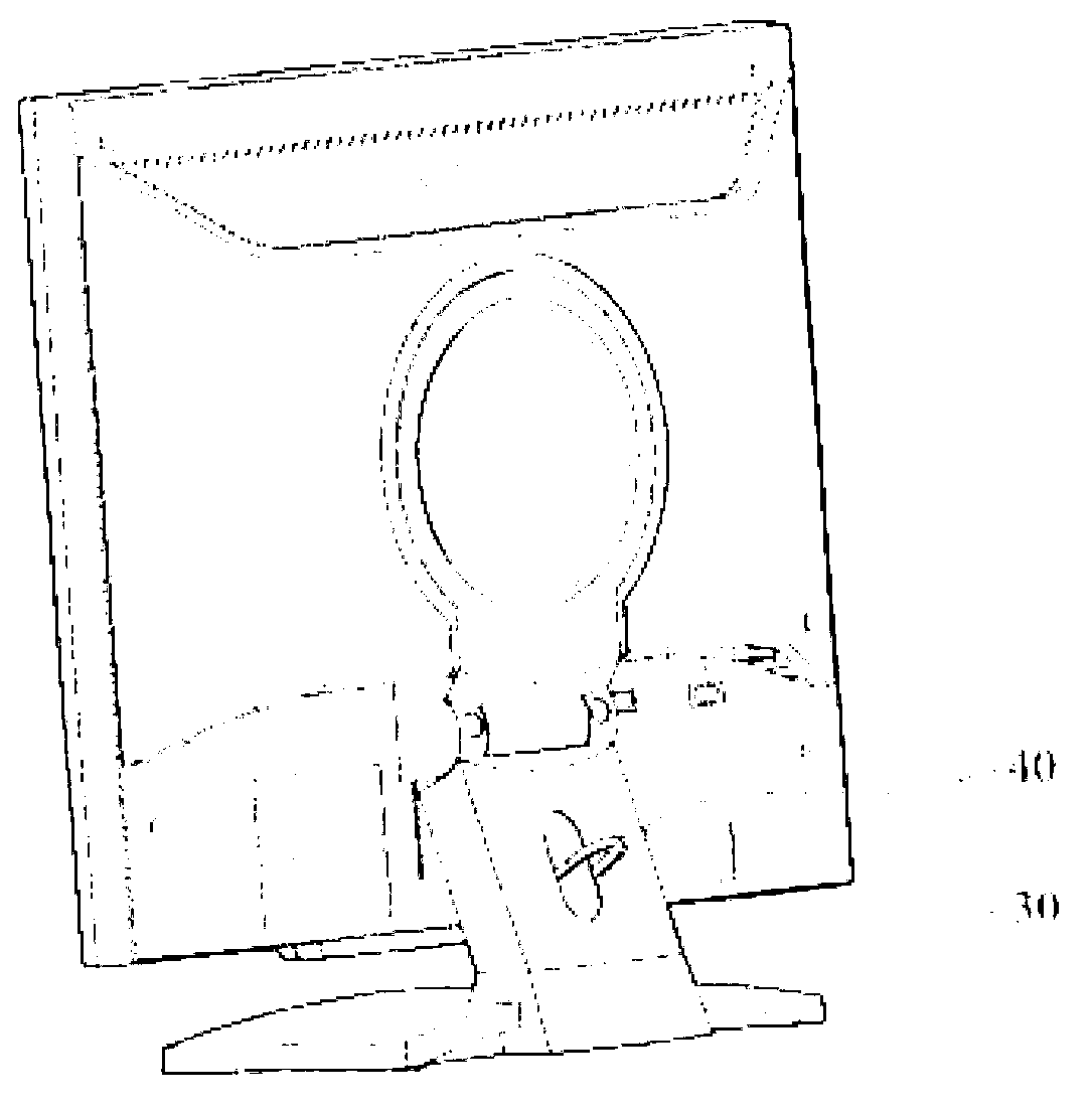
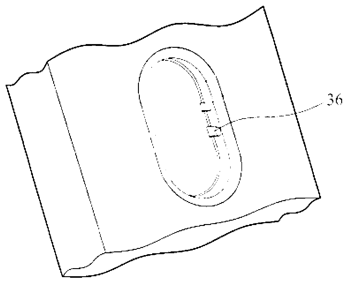
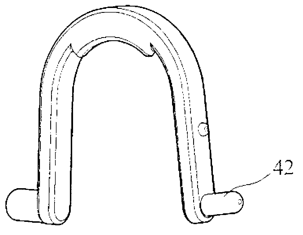
[0029] Please see Figure 4 , Figure 4 It is a structural schematic diagram of the display of the present invention. The display 100 includes a display body 10 , a cable management structure connected to the display body 10 , and a base 20 . The cable management structure includes a cable management buckle 30 and a support seat 40 . Such as Figure 5 and Figure 6 as shown, Figure 5 It is a schematic diagram of the cable management buckle of the cable management structure of the present invention, Figure 6 It is an enlarged schematic view of the first elastic arm of the cable management buckle of the present invention. The wire management button 30 has a button body 31 and two first elastic arms 32 connected with the button body 31. The button body 31 has a U...


PUM


Abstract

The invention provides a line sorting structure, which is characterized in that the line sorting structure comprises a line sorting buckle and a supporting base, wherein the line sorting buckle is provided with a buckle body and a first elastic arm connected with the buckle body; the supporting base is provided with a shaft hole and a second elastic arm corresponding to the first elastic arm; the first elastic arm can separately penetrate through the shaft hole and can be rotatably inserted into the second elastic arm; the second elastic arm is used for clamping the first elastic arm; when the first elastic arm and the second elastic arm have first opposite positions, the line sorting buckle and the supporting base are at a separable state; when the first elastic arm and the second elastic arm have second opposite positions, the line sorting buckle and the supporting base are at a non-separable state; and the second elastic arm stops the first elastic arm from moving towards the shaft hole. The line sorting structure disclosed by the invention utilizes a clamping hook between the first elastic arm and the second elastic arm to prevent the line sorting buckle from being released from the supporting base and improve the utilization reliability of a product.

Description

technical field [0001] The invention relates to a cable management structure, in particular to a cable management structure applied to a display. Background technique [0002] The appearance of display devices such as LCD monitors and LCD TVs has become the mainstream in order to meet the requirements of end users. However, in pursuit of light, thin, short and multiple appearances, the internal structure design must be coordinated with changes to strengthen the structure. Loading the weight of the whole product and the external force acting on it, therefore, under the consideration of product cost and functionality, the design difficulty is getting higher and higher, so that the manufacturing process must be relatively improved to meet the diversified design requirements. [0003] The line management structure in the current known technology has such Figure 1 to Figure 3 In the structure shown, the display has a cable management buckle 40, and the cable management buckle 40...

Claims


Application Information

Patent Timeline
Patent Type & Authority Applications(China)
IPC IPC(8): G06F1/16G09F9/00
Inventor 徐年宗卓俊荣林信宏林世安
Owner QISDA SUZHOU
Why Eureka
Try Eureka