
Mechanical lifting seat

A seat and machinery technology, applied in the field of mechanical lift seats, can solve the problems of high cost and complex structure, and achieve the effect of simple and elegant structure

Inactive Publication Date: 2013-02-20
方龙
View PDF0 Cites 3 Cited by
  • Summary
  • Abstract
  • Description
  • Claims
  • Application Information

AI Technical Summary

Problems solved by technology

[0002] The height of the traditional seat is fixed, and the height cannot be adjusted to meet the needs of different users
However, most lift seats on the market are lifted and lowered by hydraulic pressure, which has a complicated structure and high cost.

Method used


Image

  • Mechanical lifting seat
  • Mechanical lifting seat

Examples


Embodiment 1

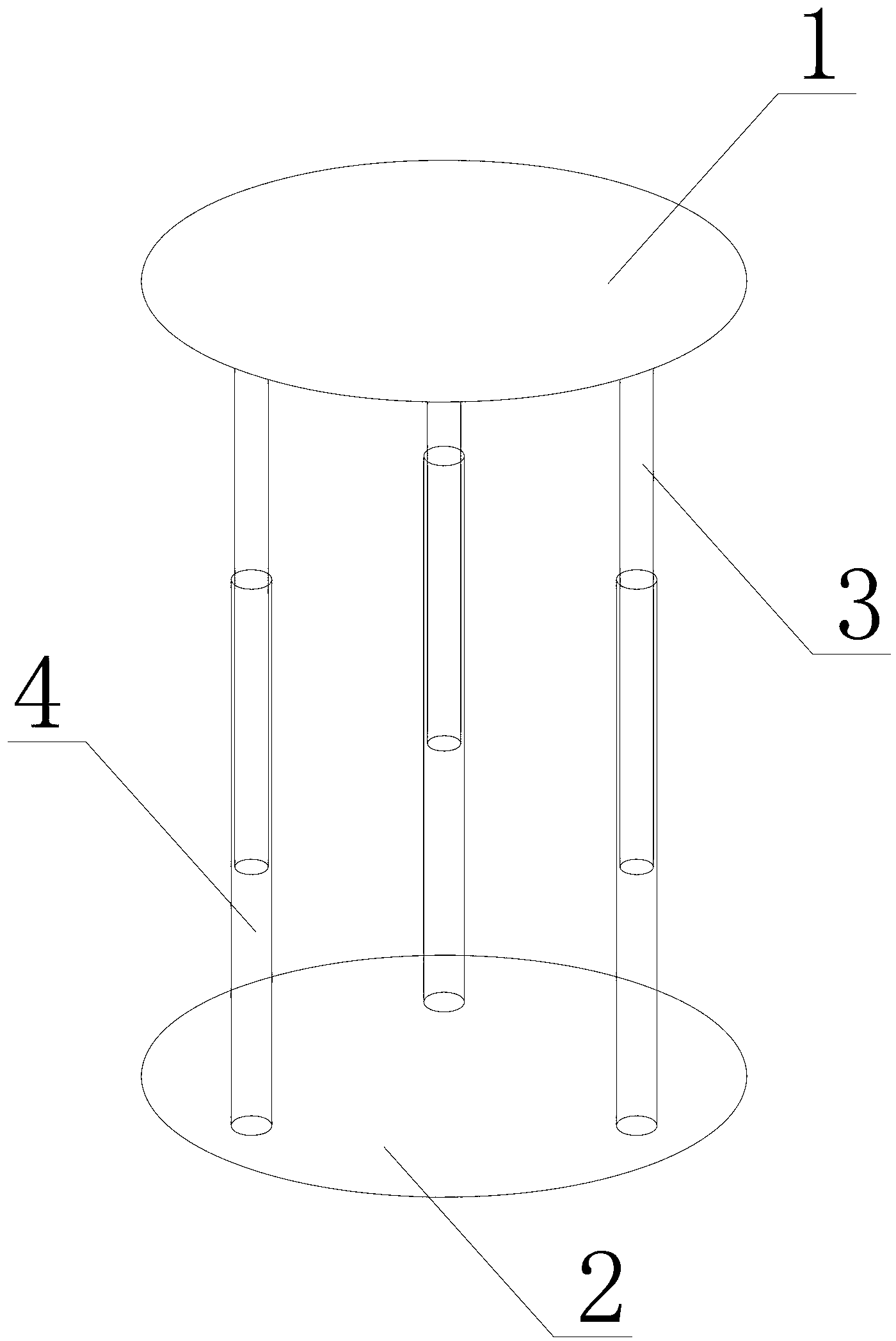
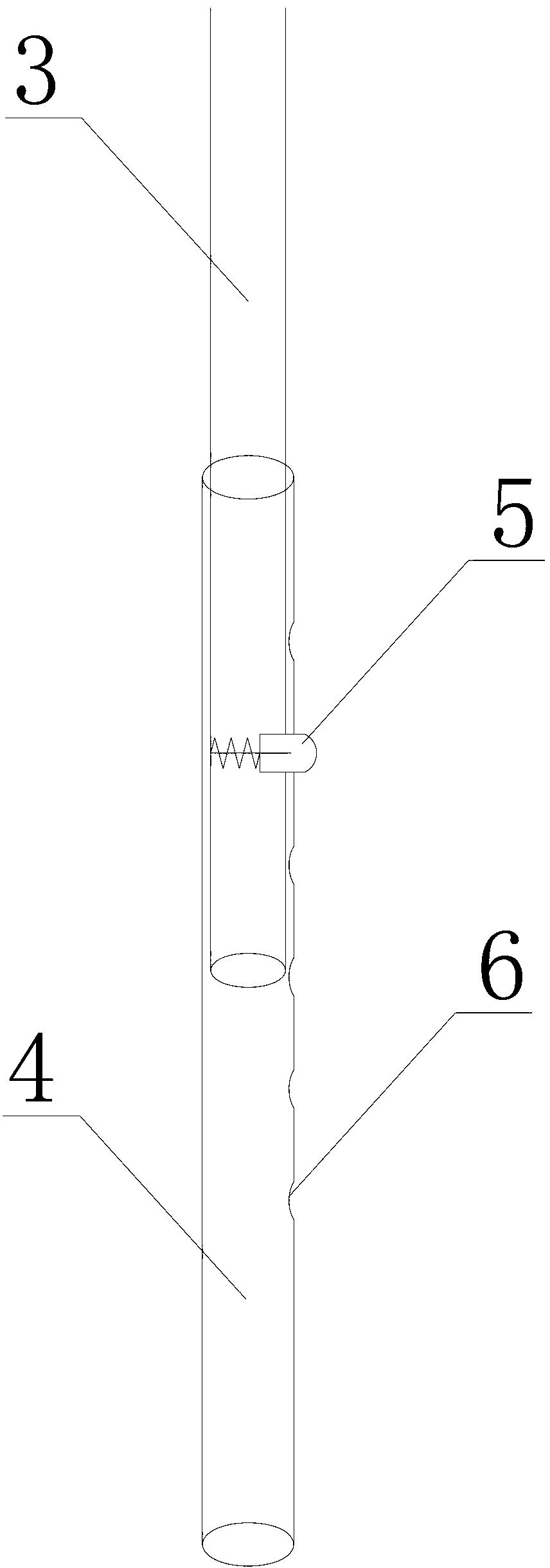
[0009] A mechanical lift seat includes a seat surface 1, a base 2, an intubation tube 3 and a sleeve tube 4. The intubation tube 3 is located at the lower part of the chair surface 1, the sleeve tube 4 is located at the upper part of the base 2, the intubation tube 3 is located at the upper part of the sleeve tube 4, and the inner diameter of the sleeve tube 4 is slightly larger than the outer diameter of the intubation tube 3; the intubation tube 3 is provided with an elastic pin 5 , Pin holes 6 are evenly distributed on the casing 4 .

[0010] When the user needs to adjust the height of the seat, first press the elastic pin 5 into the intubation tube 3, adjust the relative position of the intubation tube 3 and the sleeve tube 4 in the vertical direction, so that the elastic pin 5 and the pin holes 6 of different heights are interlocked and fixed. Can. When the user needs to raise the height of the seat, the elastic pin 5 is adjusted to the upper pin hole 6 . On the contrar...


PUM


Abstract

The invention discloses a mechanical lifting seat. The mechanical lifting seat comprises a seat face, a base, an inserting pipe and a sleeving pipe, wherein the inserting pipe is arranged on the lower portion of the seat face, the sleeving pipe is arranged on the upper portion of the seat face, the inserting pipe is arranged on the upper portion of the sleeving pipe, the inner diameter of the sleeving pipe is slightly larger than the outer diameter of the inserting pipe, an elastic pin is arranged on the inserting pipe, and pin holes are evenly distributed on the sleeving pipe. According to the mechanical lifting seat, the height of the seat can be adjusted through occluding fixing of the elastic pin and different pin holes, so that different requirements of a user can be met, and the seat is simple and elegant in structure, convenient and practical to operate and humanized.

Description

technical field [0001] The invention relates to a seat, in particular to a mechanical lifting seat. Background technique [0002] The height of the traditional seat is fixed, and the height cannot be adjusted to meet the needs of different users. However, the vast majority of lift seats on the market are lifted by hydraulic pressure, which has a complex structure and high cost. Contents of the invention [0003] Technical problem to be solved: the present invention provides a mechanical lift seat for the deficiencies of traditional seats and most existing lift seats. [0004] Technical solution: The present invention provides a mechanical lift seat, including a seat surface, a base, an intubation tube and a sleeve. The intubation tube is located at the lower part of the chair surface, the sleeve tube is located at the upper part of the base, and the intubation tube is located at the upper part of the sleeve tube. [0005] Beneficial effects: because the present inventio...

Claims


Application Information

Patent Timeline
Patent Type & Authority Applications(China)
IPC IPC(8): A47C3/34
Inventor 方龙徐佳栋
Owner 方龙
Learn More