Fan

A fan and base technology, applied in the field of household fans, can solve the problems of difficult positioning, damage to the rotating structure, easy to get stuck, etc.

Inactive Publication Date: 2013-02-13
任文华
View PDF8 Cites 1 Cited by
  • Summary
  • Abstract
  • Description
  • Claims
  • Application Information

AI Technical Summary

Problems solved by technology

This kind of fan improves the safety of use, but when this kind of fan is rotated, disassembled or installed, it is not easy to locate, get stuck or damage the rotating structure

Method used


Image

  • Fan
  • Fan
  • Fan

Examples


Embodiment Construction

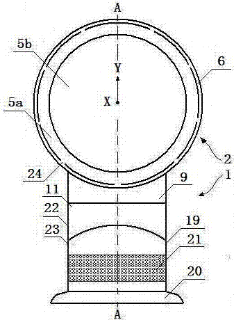
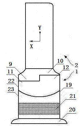
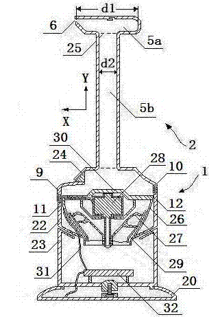
[0025] Figure 1 is a schematic view of the fan of the present invention viewed from the front of the device, figure 2 Yes figure 1 Side view of the fan shown, image 3 shown figure 1 The internal structure of the fan shown. In each figure, the axis Y represents the height direction of the fan, that is, the longitudinal direction, and the axis X represents the direction perpendicular to the height direction of the fan, that is, the horizontal direction. from Figure 1 to Figure 3 As can be seen in the figure, this fan includes a base 1 and a nozzle 2 arranged on the base 1; the base 1 includes a base body 19 and a base 20 located below the base body, the base body 19 has a side wall, and the side wall includes an air inlet 21, The air inlet 21 is in the form of a grid hole; the base body 19 includes an impeller housing 26, an impeller 27 positioned within the impeller housing and a motor 28 that drives the impeller to rotate; A blade and the shroud 29 that is connected t...


PUM


Abstract

A fan includes a base part and a nozzle mounted on the base part, wherein the base part includes an outlet for outputting airflow; and the nozzle includes an inlet for inputting airflow, an internal cavity for receiving airflow and an exhaust port for outputting airflow. The fan is characterized in that the nozzle can be detached in a manner that the nozzle can horizontally and linearly slide relative to the base part. The nozzle of the fan can be conveniently and reliably detached from or mounted on the base part.

Description

technical field [0001] The invention relates to a fan. In particular, but not exclusively, the present invention relates to a domestic fan, such as a domestic desk fan, for increasing air circulation and air flow in homes, offices and other environments. Background technique [0002] A traditional household fan typically consists of a motor and a set of blades or impellers that are driven in rotational motion by the motor. The set of blades is typically located within a cage that allows airflow to pass through, yet prevents human access to the rotating blades. But in some cases, this kind of fan also has the danger that the human body touches the group of rotating blades. [0003] On December 7, 2011, the Chinese patent with the authorized announcement number CN101825106 B (application number: 201010130004.3) disclosed a fan without exposed blades. This fan includes a base and a nozzle arranged on the base. The nozzle includes an internal cavity and an exhaust port for re...

Claims


Application Information

Patent Timeline
Patent Type & Authority Applications(China)
IPC IPC(8): F04B41/06F04F5/46F04F5/44
Inventor 任文华
Owner 任文华
Why Eureka
Try Eureka