Automotive body profile repairing device
A technology for shape repair and automobile body, applied in the field of automobile body shape repair devices, can solve the problems of inconvenient operation, difficult to smooth and smooth sheet metal, time-consuming and labor-intensive, etc., and achieves the effect of good repair effect, elimination of dents, and simple operation.
- Summary
- Abstract
- Description
- Claims
- Application Information
AI Technical Summary
Problems solved by technology
Method used
Image

Examples
Embodiment 1
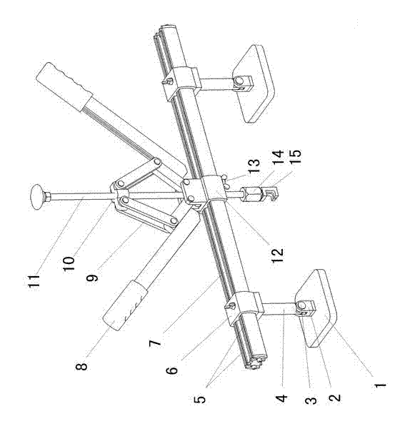
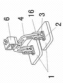
[0016] like figure 1 Shown: 1 is a support plate, a support 2 is fixedly connected to the support plate 1, and 4 is a pole, and the lower end of the pole 4 is connected to the support 2 through a pin 3 in rotation.
[0017] A crossbeam cover 6 is fixedly connected to the upper end of the pole 4, and a crossbeam 5 is provided with the crossbeam cover 6. There are two crossbeams 5, which are arranged parallel to each other and form a gap 7 in the middle. Locking bolts are arranged between the crossbeam cover 6 and the crossbeam 5 for relatively fastening the crossbeam cover 6 and the crossbeam 5 .
[0018] The above-mentioned support plate 1, pole 4, and beam cover 6 are two groups, and a support sleeve 12 is set on the beam 5 between the two beam sets 6 and a fastening bolt 13 is set. After tightening the fastening bolt 13, the support sleeve can be made 12 is relatively fixed with crossbeam 5. Above the support sleeve 12, a four-bar linkage mechanism 9 is connected by a pin ...
Embodiment 2
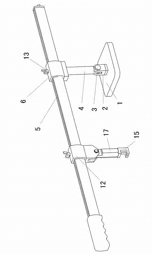
[0022] like image 3 Shown: 1 is a support plate, a support 2 is fixedly connected to the support plate 1, and 4 is a pole, and the lower end of the pole 4 is connected to the support 2 through a pin 3 in rotation.
[0023] A crossbeam cover 6 is fixedly connected to the upper end of the pole 4 and fastening bolts 13 are arranged, and a crossbeam 5 is provided with the crossbeam cover 6 . A supporting sleeve 12 is sleeved on the beam 5, and fastening bolts are also arranged on the supporting sleeve 12. The bottom of the support sleeve 12 is connected with a pull rod 17 by a bearing pin, and the lower end of the pull rod 17 is rotatably connected with a connecting end 15, which can be threadedly connected, and the connecting end 15 is hooked to form a lever-type lifting mechanism.
[0024] When in use, place the support plate 1 at an appropriate position next to the depression on the surface of the car, weld a hanging piece at the depression, hang the connecting end 15 on the ...
Embodiment 3
[0026] like Figure 4 Shown: 1 is a support plate, a pole 4 is fixed on the middle part of the support plate 1, and the pole 4 is fixedly connected with a fixed sleeve 20 through a connecting beam 28, and a vertical rod 30 is inserted in the fixed sleeve 20, and the vertical rod 30 is There is a lifting block 21 above the fixed sleeve, and there are lifting shafts 27 and 24 on both sides of the lifting block 21. The pressing rod 24 is connected to the pole 4 through the rotating shaft 26. The end of the pressing rod 24 is connected to the lifting shaft. 27 is connected, and the vertical rod 30 can be driven to move up and down in the fixed sleeve 20 by the depression rod 24.
[0027] The lower end of the vertical rod 30 is connected with a connecting end 15 through a connecting nut 18. The connecting end 15 is in the shape of a circular platform. On the vertical rod 30, a spring 19 is set below the fixed sleeve 20. The upper end of the spring 19 leans against the lower end of ...
PUM
 Abstract
Description
Claims
Application Information
 - R&D
- Intellectual Property
- Life Sciences
- Materials
- Tech Scout
- Unparalleled Data Quality
- Higher Quality Content
- 60% Fewer Hallucinations
Browse by: Latest US Patents, China's latest patents, Technical Efficacy Thesaurus, Application Domain, Technology Topic, Popular Technical Reports.
© 2025 PatSnap. All rights reserved.Legal|Privacy policy|Modern Slavery Act Transparency Statement|Sitemap|About US| Contact US: help@patsnap.com