
Fluid loss monitoring device and method

A technology for monitoring device and fluid flow, used in gas/liquid distribution and storage, piping systems, mechanical equipment, etc., to solve problems such as inaccurate water flow measurement, water loss, and increased manufacturing costs

Active Publication Date: 2014-11-12
刘金玉
View PDF3 Cites 0 Cited by
  • Summary
  • Abstract
  • Description
  • Claims
  • Application Information

AI Technical Summary

Problems solved by technology

[0004] However, when the sealing performance of the valve is reduced, or the water flow is actively reduced for human reasons, the water flow through the water flow measuring device is very small, and the energy of the water flow is not enough to drive the impeller of the water flow measuring device to rotate, and the water flow measuring device cannot Measure the flowing water, resulting in inaccurate measurement of water flow; furthermore, the flow control device cannot control the on-off of the tap water pipe according to the actual water flow, resulting in abnormal loss of water
In the prior art, although it is possible to improve the manufacturing accuracy of the impeller of the water flow measuring device, reduce the energy required to drive the impeller to rotate, and reduce the starting flow rate of the water flow measuring device, this makes the manufacturing cost of the water flow control device Substantial increase, unable to meet actual needs
Chinese patent document CN202149794U (patent number: ZL201120277718.7) discloses another water flow measurement device, which reduces the initial flow of the water flow measurement device by concentrating the energy of the water flow to form a jet, but still requires an energy to drive the impeller Rotation, so that the starting flow of the flow measuring device cannot be further reduced

Method used


Image

  • Fluid loss monitoring device and method
  • Fluid loss monitoring device and method

Examples


Embodiment Construction

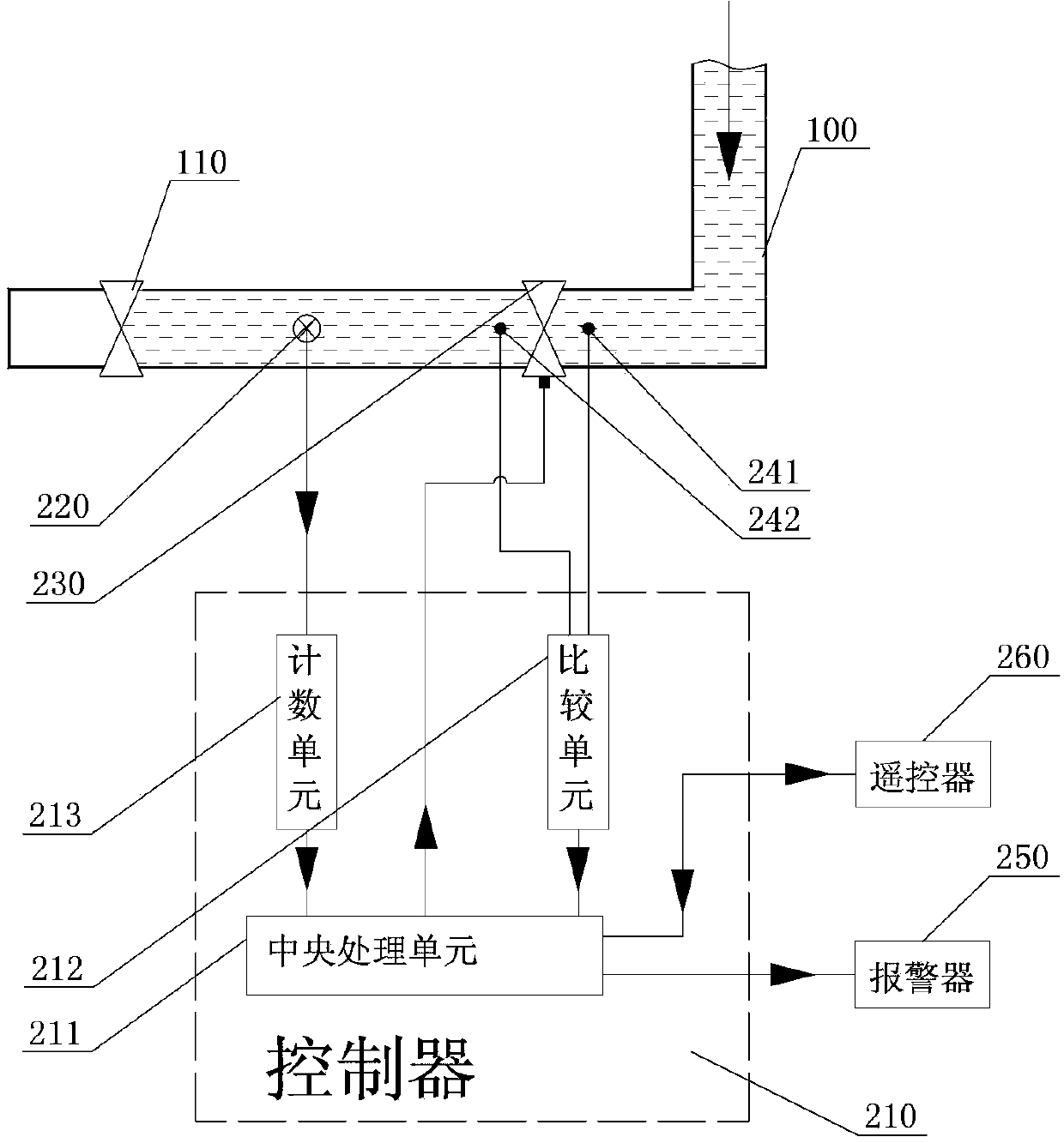
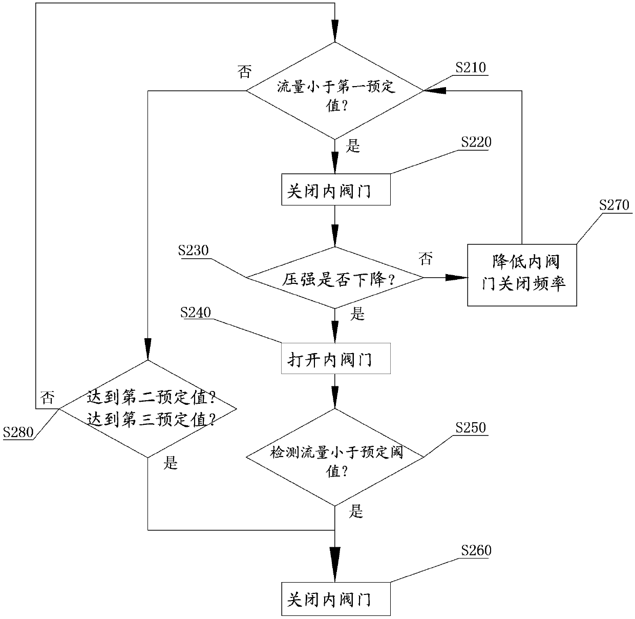
[0040] The core of the present invention is: by detecting the pressure of the fluid between the terminal valve and the inner valve, combined with the fluid flow, the accurate judgment and control of the pipeline state can be realized, and the quantitative judgment of the fluid flow can be converted into whether the pressure is reduced and the fluid flow rate is reduced. The qualitative judgment of whether the flow rate is less than a predetermined threshold can overcome the shortcomings of the existing quantitative detection technology and improve the accuracy of judgment.

[0041] The technical solution provided by the present invention will be described in detail below in conjunction with the accompanying drawings. The description in this part is only exemplary and explanatory, and should not be regarded as limiting the technical content disclosed in the present invention.

[0042] It should be noted that in this document, the inner side refers to the side close to the fluid so...


PUM


Abstract

The invention discloses a device for monitoring pipeline fluid. The device comprises an electric control valve arranged on a pipeline, a flow measurer used for detecting partial fluid flow between a terminal valve and the electric control valve, two pressure transducers used for detecting pressures at the inner side and the outer side of the electric control valve, and a controller capable of controlling the electric control valve according to a predetermined strategy. The predetermined strategy comprises the following steps: when the detection flow of the flow measurer is smaller than a first predetermined value, closing the electric control valve; determining whether a predetermined pressure difference exists between the inner side and the outer side of the electric control valve according to detecting signals of the two pressure transducers; when the predetermined pressure difference is judged to exist, opening the electric control valve; and judging whether the detection flow of the flow measurer is smaller than a predetermined threshold again, and closing the electric control valve and giving an alarm when the detection flow of the flow measurer is smaller than the predetermined threshold. Under the condition of keeping lower cost, the device for monitoring the pipeline fluid is used for more accurately controlling the switching on or off of the pipeline according to the actual fluid flow. The invention also discloses a method or monitoring the pipeline fluid.

Description

technical field [0001] The invention relates to a fluid monitoring technology, in particular to a fluid loss monitoring device and a fluid loss monitoring method. Background technique [0002] In daily life and industrial production, appropriate pipelines are usually laid to control the flow direction of water, oil or other fluids. In order to facilitate control and meet the needs of actual life and production, valves are usually installed on the pipeline to control the flow of fluid; open the valve to allow the fluid to flow, and close the valve to stop the flow of fluid. Although the flow of fluid can be controlled through the valve, the valve has a certain sealing performance, and the valve sealing performance may be reduced due to wear after a period of use. Therefore, in the case where the sealing performance of the valve is deteriorated, even if the valve is closed, the fluid will flow through the valve, resulting in an abnormal loss of the fluid. [0003] In order t...

Claims


Application Information

Patent Timeline
Patent Type & Authority Patents(China)
IPC IPC(8): F17D3/01
Inventor 刘金玉王殿生杜新祥任金恒李庆林闫国亮
Owner 刘金玉
Learn More