
Technique for cooling deep mining area by using ground temperature of shallow goaf and waste roadway

A goaf and deep technology, which is used in mine/tunnel ventilation, mining equipment, earth-moving drilling, etc., can solve the problem of pre-cooling air volume, wind resistance adjustment, difficulty in air flow adjustment, and heat exchange area between wind flow and surrounding rock in the goaf. Small problems such as optimizing the ventilation system management mode, improving the ventilation management level, and consolidating the effect of cooling and pre-cooling

Active Publication Date: 2013-01-30
SINOSTEEL MAANSHAN INST OF MINING RES
View PDF5 Cites 13 Cited by
  • Summary
  • Abstract
  • Description
  • Claims
  • Application Information

AI Technical Summary

Problems solved by technology

Xiangxi Gold Mine, Jiudian Gold Mine, Jinqingding Mine and other mines tried to use the low-temperature ground temperature natural resources of abandoned underground shafts and goafs, but did not adjust the pre-cooling air volume and wind resistance
The ventilation resistance of the goaf is large, the passing air volume is small, and the heat exchange area between the air flow and the surrounding rock in the goaf is small, so that the convective heat transfer between the ground temperature and the air flow is low, and the pre-cooling air volume is small, so that the air temperature entering the deep part is still high. The cooling effect on the entire ventilation system is not obvious, and it is difficult to achieve the purpose of improving the working environment and reducing ventilation energy consumption. At the same time, the air flow in the goaf is reversed in winter and summer, and it is difficult to adjust the air flow

Method used


Image

  • Technique for cooling deep mining area by using ground temperature of shallow goaf and waste roadway
  • Technique for cooling deep mining area by using ground temperature of shallow goaf and waste roadway

Examples


Embodiment Construction

[0026] In order to further describe the present invention, the technology for cooling deep mining areas by using the ground temperature of shallow mined-out areas and waste roadways of the present invention will be further described in detail in conjunction with the accompanying drawings and examples below.

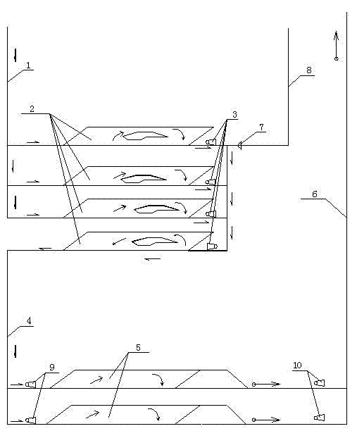
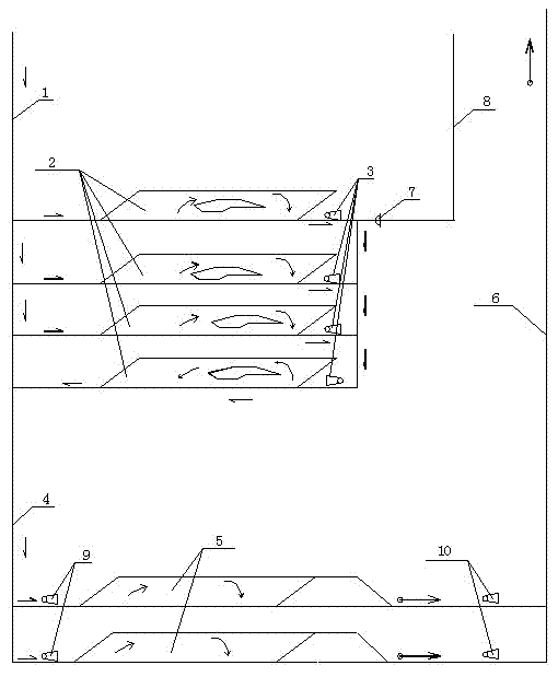
[0027] Depend on figure 1 The schematic diagram of the deep mining area cooling system using the shallow goaf and waste roadway ground temperature to cool the deep mining area with all the air flow precooling of the deep air inlet source is shown. The shallow air intake shaft 1 goes down, and under the negative pressure of the pre-cooling fan 3 in the upper (n-1) shallow gobs and the middle section where the waste roadway 2 is located (the pre-cooling fan is pulled out), the mine All the fresh air flow into the shallow goaf and the abandoned roadway 2 is introduced into the shallow mined-out area and the low-temperature rock mass of the abandoned roadway 2 for heat exchan...


PUM


Abstract

The invention discloses a technique for cooling a deep mining area by using the ground temperature of a shallow goaf and a waste roadway. An air intake fan station (9) is arranged outside an air intake port of a deep operating middle section (5); a return fan station (10) is arranged outside an air outlet port of the deep operating middle section (5); the air intake fan station (9) is communicated with a deep downcast shaft (4); the return fan station (10)is communicated with an air return shaft (6); pre-cooling fans (3) are arranged at all the exits of the shallow goaf and the waste roadway (2); and an air door (7) is arranged on a natural ventilation air passage (8) shared by the shallow goaf and the waste roadway (2). According to the invention, an air flow circuit and the pre-cooling fans (3) are adopted to adjust the downcast air flow, and through the technique, the high-temperature air flow can be totally or partially pre-cooled in summer so as to reduce the wind enthalpy which enters the deep high-temperature area and to improve the heat extraction and cooling abilities of the system. In winter, the pre-cooling fans are turned off and the heat accumulated in summer is expelled through natural ventilation. Therefore, the technique realizes alternating multiple heat balance and use in winter and summer in a mine.

Description

technical field [0001] The invention relates to a cooling technology for underground non-coal solid mines, which is suitable for ventilation and cooling of mines with low-temperature gobs and waste roadways in the shallow part and high-temperature thermal damage non-coal (non-radioactive) solid mines in the deep part. Background technique [0002] The earth's rock mass is roughly divided into three circles: the variable temperature zone, the constant temperature zone, and the heating zone. The thickness of the variable temperature zone and the constant temperature zone is generally only 30-50m thick. According to the geothermal temperature increase rate, the temperature of the rock mass increases with depth. During the downward mining of the mine, a large number of goafs and abandoned roadways were left in the upper part. Many of these goafs and abandoned roadways were connected with the surface to form a natural ventilation air path. ~330m) has gradually become a temperatur...

Claims


Application Information

Patent Timeline
IPC IPC(8): E21F1/00E21F3/00
Inventor 吴冷峻居伟伟周伟黄寿元贾敏涛蔡建华
Owner SINOSTEEL MAANSHAN INST OF MINING RES
Learn More