Eureka AIR delivers breakthrough ideas for toughest innovation challenges, trusted by R&D personnel around the world.

Holder of concrete vibrating bar

A vibrating rod and gripper technology, which is used in construction, building construction, and processing of building materials, etc., can solve problems such as worker's hand discomfort, arm and hand injury, etc.

Inactive Publication Date: 2013-01-23
江苏大众电器有限公司
View PDF0 Cites 3 Cited by
  • Summary
  • Abstract
  • Description
  • Claims
  • Application Information

AI Technical Summary

Problems solved by technology

Due to the high-speed vibration of the rod body, the workers' hands are more uncomfortable, and the workers' arms and hands are easy to be injured.

Method used


Image

  • Holder of concrete vibrating bar

Examples


Embodiment Construction

[0013] The following descriptions are only preferred embodiments of the present invention, and therefore do not limit the protection scope of the present invention.

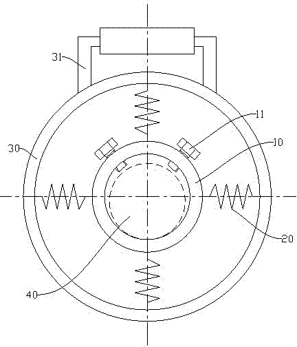
[0014] Examples, see figure 1 As shown: the concrete vibrating rod holder includes an inner ring 10 and an outer ring 30 , and the inner ring 10 and the outer ring 30 are connected by at least three springs 20 . When in use, the connecting hose 40 is passed through the inner ring 10, and the worker controls the movement of the connecting hose 40 by controlling the outer ring 30 of the concrete vibrator holder, and then controls the movement of the rod body. In this way, the vibration received by the inner ring 10 is effectively filtered by the spring 20 so that the vibration will not be transmitted to the outer ring 30 .

[0015] Optimally, the springs 20 are distributed in a circular array along the center of the inner ring 10 . In this way, it is convenient to make the inner ring 10 and the outer ring 30 conc...


PUM


Abstract

The invention discloses a holder of a concrete vibrating bar. The holder comprises an inner ring and an outer ring, wherein the inner ring and the outer ring are connected through at least three springs. After optimizing, four springs are distributed in a circular array form along the center of the inner ring; an adjusting screw is arranged on the inner ring; a handle is arranged on the outer ring. The holder of the concrete vibrating bar has the advantage of effectively reducing vibration hurt of a worker in the process of using the concrete vibrating bar.

Description

technical field [0001] The invention relates to the technical field of construction machinery accessories, in particular to a concrete vibrating rod holder. Background technique [0002] The concrete vibrating rod includes a hollow rod body, and a vibrating device is arranged inside the rod body, and the device is connected to a power device through a connecting hose. That is, the power device drives the vibrating device to move, causing the rod to vibrate at a high frequency. In this way, the rod body is inserted into the well-mixed concrete pouring component, and the air bubbles in the concrete are eliminated through vibration, so that the concrete is densely combined, and the phenomenon of honeycomb pitting of the concrete is eliminated. When it is in use, workers mostly control the movement of the stick by holding the connecting hose. Due to the high-speed vibration of the rod body, the hands of the workers are more uncomfortable, and the arms and hands of the workers ...

Claims


Application Information

Patent Timeline
IPC IPC(8): E04G21/08
Inventor 夏振宇
Owner 江苏大众电器有限公司
Why Eureka
Eureka Blog
Learn More