
Device and method for preventing rotary mechanism from automatically rotating

A slewing mechanism and automatic rotation technology, applied in the direction of cranes, etc., can solve the problems of difficulty in installing workpieces, safety accidents, and difficulty in installing and positioning of hoisted objects, and achieve the effect of improving convenience and safety.

Active Publication Date: 2014-12-10
XUZHOU HEAVY MASCH CO LTD
View PDF5 Cites 0 Cited by
  • Summary
  • Abstract
  • Description
  • Claims
  • Application Information

AI Technical Summary

Problems solved by technology

On the existing hoisting machinery, with the increase of tonnage, the length and weight of the outrigger are also increasing, so it is inevitable that the outrigger has a certain side bend, so there is a horizontal axis with the center of rotation as the axis. Center, the projected length of the outrigger on the horizontal plane is the torque of the force arm; this leads to the phenomenon that the slewing mechanism automatically rotates when the slewing brake is turned on and the slewing handle is not actuated, and the lighter ones bring great harm to the user when installing the workpiece Difficult, severe ones can lead to serious safety accidents
This phenomenon is more obvious when the crane is in the hoisting state, which will eventually bring great difficulties and dangers to the installation of the hoisted object.

Method used


Image

  • Device and method for preventing rotary mechanism from automatically rotating
  • Device and method for preventing rotary mechanism from automatically rotating
  • Device and method for preventing rotary mechanism from automatically rotating

Examples


Embodiment Construction

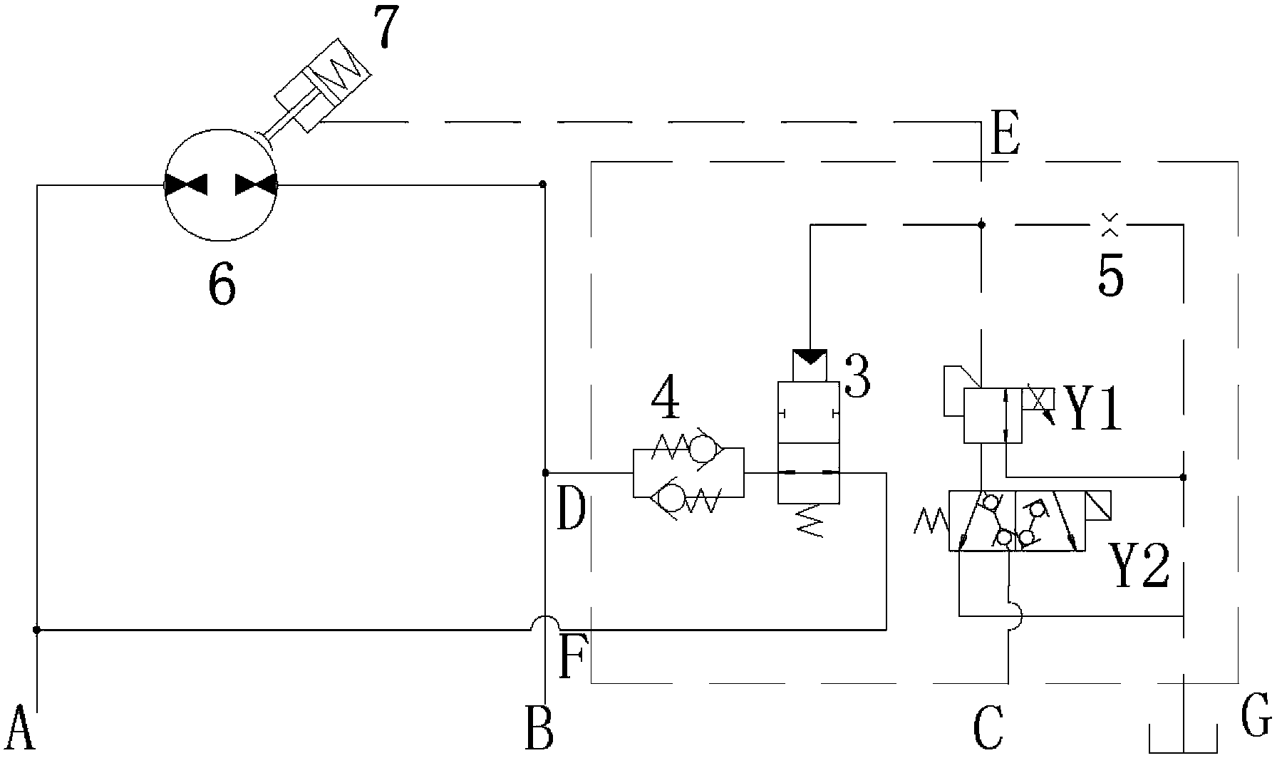
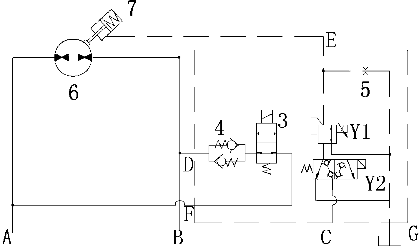
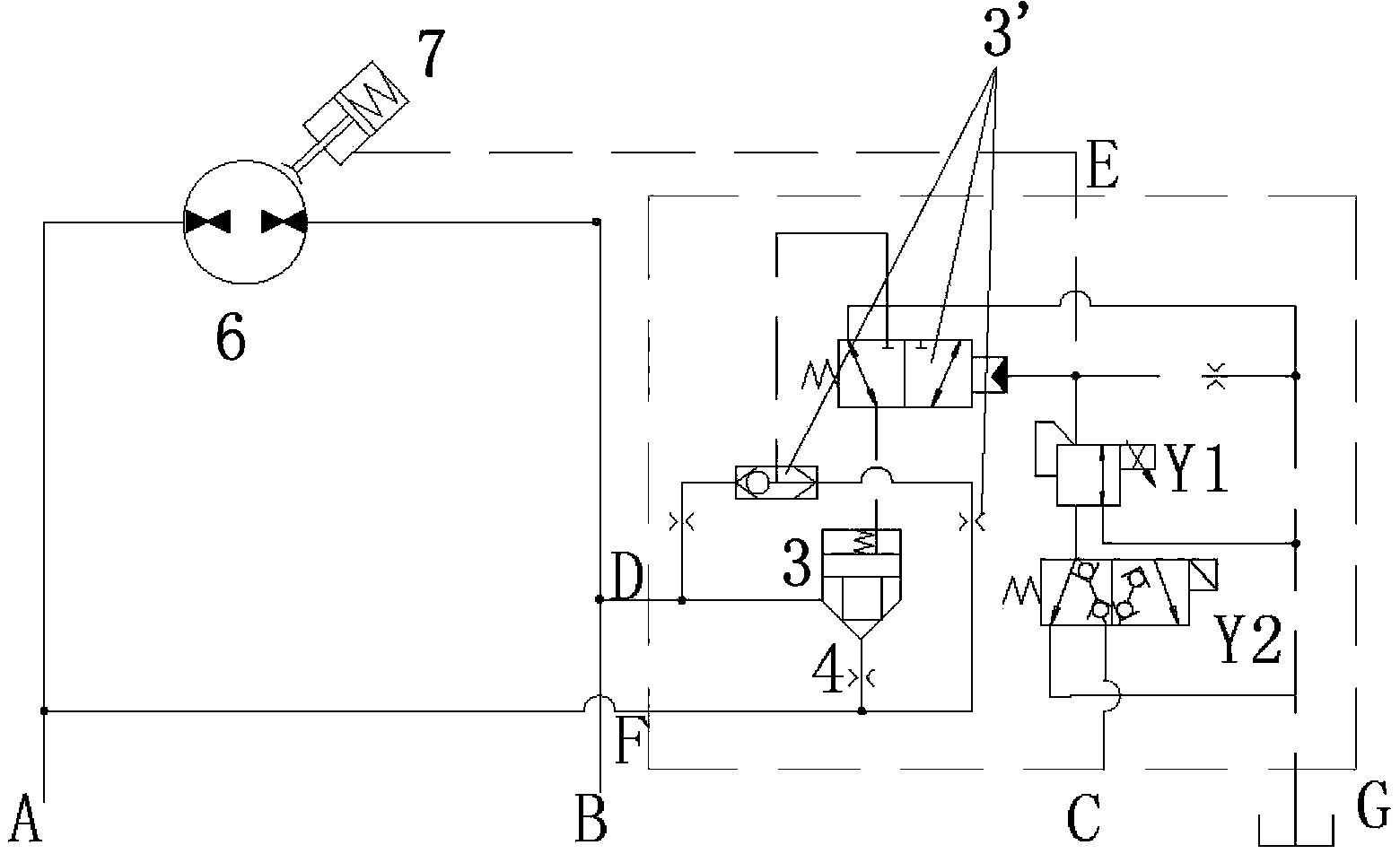
[0046] figure 1It shows the device and its hydraulic principle for preventing the automatic rotation of the slewing mechanism of the crane according to the present invention. The slewing mechanism of the crane usually includes a slewing handle, an oil tank, a slewing brake 7 and a slewing motor 6, etc. The components of the device are connected in a known manner to form an oil circuit (for example, the oil circuit of a slewing mechanism in existing cranes). According to this principle, the device to prevent the automatic rotation of the slewing mechanism of the crane includes the electric proportional pressure reducing valve Y1, the switch valve Y2 and the first hydraulic control part 3, etc., and the electric proportional pressure reducing valve Y1 set in the device is used to realize the control The opening time of the slewing brake 7 prevents the slewing mechanism from automatically rotating. The specific working principle is as follows:

[0047] The device for preventing...


PUM


Abstract

The invention relates to a device for preventing a rotary mechanism from automatically rotating. The rotary mechanism comprises a rotary handle, an oil tank, a rotary brake (7), a rotary motor (6) and five oil holes (C-G), which form a hydraulic oil path. The device is characterized by comprising an electric proportion reducing valve (Y1), a switch valve (Y2) and a first hydraulic control part (3), wherein the first hydraulic control part (3) is arranged in the oil path from a first port (A) to the second oil hole (D), the electric proportion reducing valve (Y1) and the switch valve (Y2) are serially arranged in the oil path from the first oil hole (C) to the second oil hole (E), and the initial stages of the electric proportion reducing valve (Y1) and the switch valve (Y2) are electrically neutral stages. In addition, the invention also relates to a method for preventing the rotary mechanism from automatically rotating, and a crane comprising the device for preventing the rotary mechanism from automatically rotating.

Description

technical field [0001] The present invention relates to a device and a method for preventing automatic rotation of a slewing mechanism of a crane or the like, and in particular the invention also relates to a crane comprising the device. Background technique [0002] Solving the problem of automatic rotation of the slewing mechanism is an important problem that every hydraulic designer must face. On the existing hoisting machinery, with the increase of tonnage, the length and weight of the outrigger are also increasing, so it is inevitable that the outrigger has a certain side bend, so there is a horizontal axis with the center of rotation as the axis. Center, the projected length of the outrigger on the horizontal plane is the torque of the force arm; this leads to the phenomenon that the slewing mechanism automatically rotates when the slewing brake is turned on and the slewing handle is not actuated, and the lighter ones bring great harm to the user when installing the wo...

Claims


Application Information

Patent Timeline
Patent Type & Authority Patents(China)
IPC IPC(8): B66C23/94
Inventor 陈向东王守伟张晓磊张盛楠
Owner XUZHOU HEAVY MASCH CO LTD
Learn More