
Facility for producing energy using a gas-cooled fast reactor

A facility and gas technology, applied in the field of fourth-generation nuclear reactors, can solve problems such as increasing operating costs

Inactive Publication Date: 2013-01-09
COMMISSARIAT A LENERGIE ATOMIQUE ET AUX ENERGIES ALTERNATIVES
View PDF5 Cites 3 Cited by
  • Summary
  • Abstract
  • Description
  • Claims
  • Application Information

AI Technical Summary

Problems solved by technology

To limit this risk, regular inspections and maintenance operations on cooling facilities are required, thus increasing operating costs

Method used


Image

  • Facility for producing energy using a gas-cooled fast reactor
  • Facility for producing energy using a gas-cooled fast reactor
  • Facility for producing energy using a gas-cooled fast reactor

Examples


Embodiment Construction

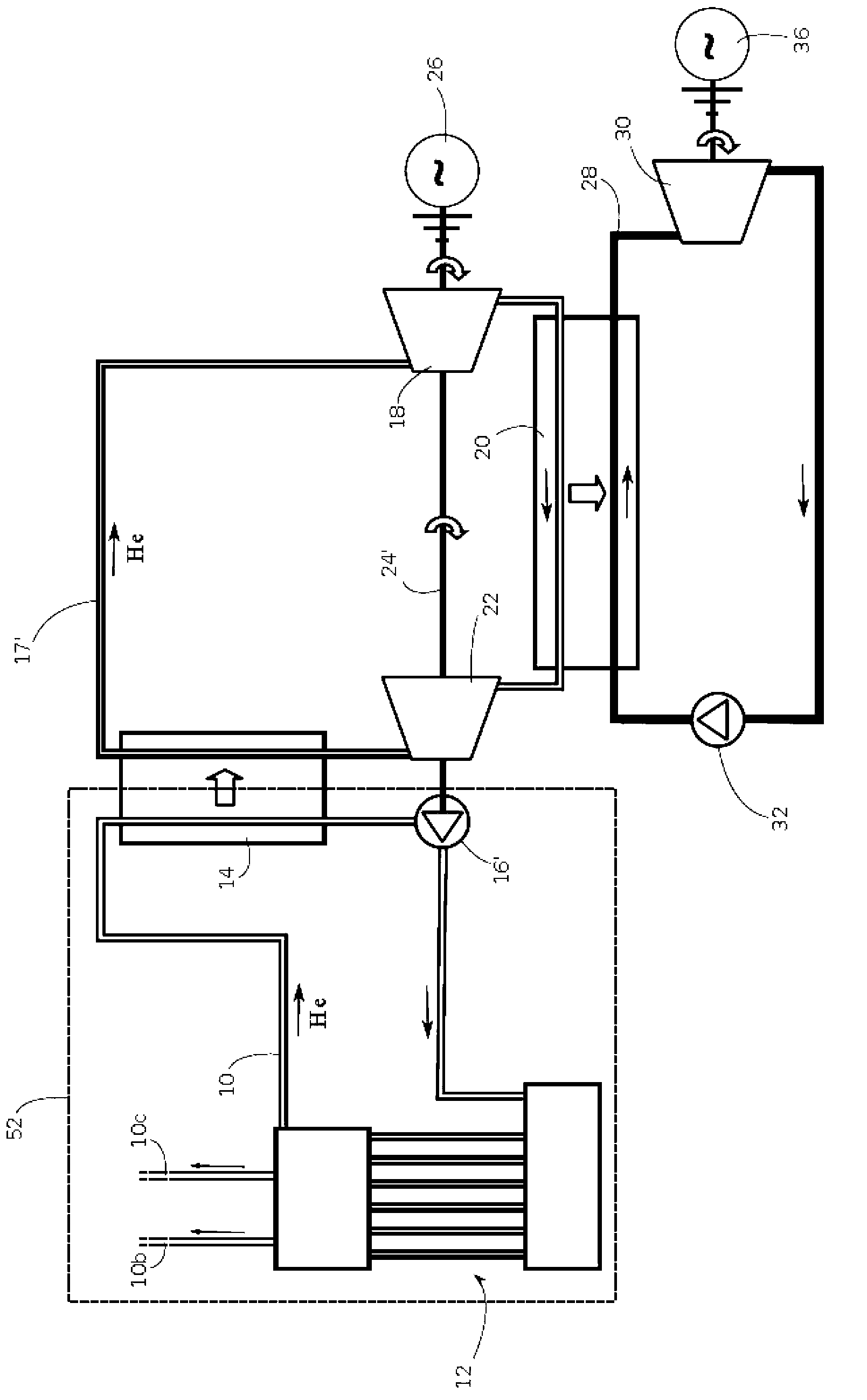
[0020] figure 2 A facility with spontaneous and passive emergency cooling capabilities is described, the same elements can be found in figure 1 found in , and are identified with the same reference numerals. "Spontaneous cooling capability" means a facility's ability to remove residual heat from a shutdown reactor (such as after an accident) without requiring specific operator or controller intervention other than reactor shutdown and alternator disconnection. To achieve this, components that serve the purpose of generating electricity during normal operation of the facility are used to cool the reactor.

[0021] compared to figure 1 A difference in the installation in the primary circuit (primary circuit) fan 10 (marked here with reference numeral 16'), is connected by the same shaft of the turbine 18 and compressor 22 in the secondary circuit (secondary circuit) 17' 24' drive. The fan 16' is therefore always connected to the turbine 18 of the secondary circuit, especial...


PUM


Abstract

The present invention relates to a facility for producing energy comprising a gas primary circuit (10) passing through a nuclear reactor (12), through a first heat exchanger (14), and through a fan (16'). An incondensable-gas secondary circuit (17') passes through the first exchanger (14), and through a turbine (18) and a compressor (22) which are mounted on one and the same shaft (24'). The fan is driven by the shaft. The gases in the primary and secondary circuits are of the same kind, and the pressure in the secondary circuit is slaved to the pressure in the primary circuit.

Description

technical field [0001] The present invention relates to fourth generation nuclear reactors, in particular those known as GFR (standing for gas-cooled fast reactor). The invention relates more particularly to the cooling of such reactors in case of accidents. [0002] A so-called "fast reactor" is a reactor that utilizes a coolant that does not slow down the neutrons released by the nuclear reactor and does not include a moderator. Background technique [0003] figure 1 A power generation facility is described from a study in the paper "CATHARE SIMULATION OF TRANSIENTS FOR THE 2400 MW GAS FAST REACTOR CONCEPT" (the conference Proceedings of ICAPP'09, Tokyo, Japan, 10-14 May 2009, P 9378) Class joint indirect loop GFR. A primary circuit 10 (with pure helium as coolant) passes through the core of a nuclear reactor 12 and via a heat exchanger 14 . The helium is kept in circulation by means of an electrically supplied fan 16 placed in the circuit between the outlet of the hea...

Claims


Application Information

Patent Timeline
Patent Type & Authority Applications(China)
IPC IPC(8): G21D3/06G21C15/18G21C1/02F02C1/05
CPCY02E30/34F02C1/05G21D3/06G21C15/28Y02E30/33G21C1/028G21C15/18Y02E30/00Y02E30/30
Inventor N.陶弗农F.本迪沃格里奥
Owner COMMISSARIAT A LENERGIE ATOMIQUE ET AUX ENERGIES ALTERNATIVES
Learn More