
Prosthesis for spinal column, instrument for its guiding and method for implantation thereof

一种假体、器械的技术

Inactive Publication Date: 2013-01-09
LFC Z O O
View PDF14 Cites 3 Cited by
  • Summary
  • Abstract
  • Description
  • Claims
  • Application Information

AI Technical Summary

Problems solved by technology

[0027] The above methods are inconvenient in their complexity and the duration of the surgical procedure

Method used


Image

  • Prosthesis for spinal column, instrument for its guiding and method for implantation thereof
  • Prosthesis for spinal column, instrument for its guiding and method for implantation thereof
  • Prosthesis for spinal column, instrument for its guiding and method for implantation thereof

Examples


Embodiment Construction

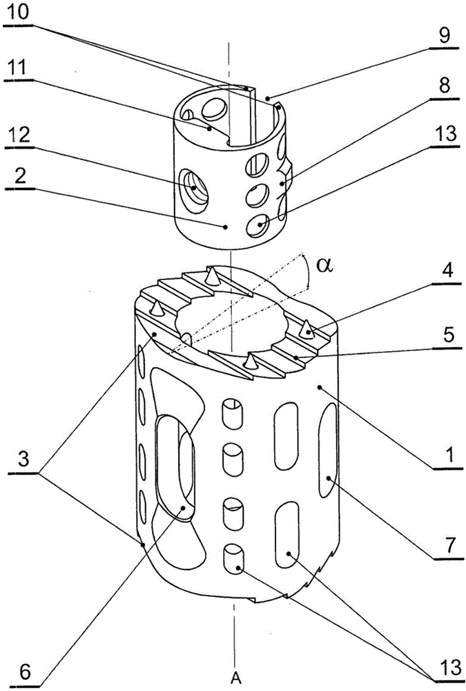
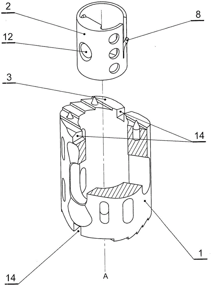
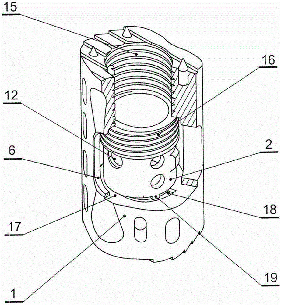
[0071] figure 1 The anterior spinal prosthesis shown consists of a main body 1 in the form of a perforated sleeve and a positioner 2 cooperating with and inside the main body 1 . The body 1 is provided on each end face 3 with four anchoring elements 4 and teeth 5 in the form of spikes. In the wall of the main body 1 corresponding to the front part of the spine, a through elongated operation hole 6 is formed, and from the side of the operation hole 6, a through positioning hole 7 is positioned, the longitudinal axis of the positioning hole 7 is parallel to the operation The longitudinal axis of the hole 6. The longitudinal axes of the operating hole 6 and the positioning hole 7 are parallel to the longitudinal axis A of the main body 1 . Each end face 3 of the main body 1 is cut in from the side of the operation hole 6 and deviates from the transverse axis of the main body 1 by an angle α of 42°, which enables it to be in the initial installation phase for inserting and ancho...


PUM


Abstract

The application relates to a prosthesis of the anterior spinal column, which consists of a perforated sleeve body provided with at least one anchoring element, teeth and overgrowth holes and a positioner (2) situated within the body (1). The body has got in its wall at least one through manipulative hole (6) and at least one through positioning hole (7) cooperating with it, whose longitudinal axes are parallel with each other, whereas the positioner is provided with at least one situating element (8) cooperating with at least one positioning hole of the body and at least one hole (12), where the length of the manipulative hole of the body corresponds to the distance between extreme locations of the positioner's hole situated within the inside diameter of the manipulative hole. At least one end face (3) of the body or / and body's wall are provided with at least one pair of opposite guidelines (14). For introducing the prosthesis into the intervertebral space a guiding instrument is used in the form of a rod ended from one side with a holder and from the other side with a shaped working element. The application relates also to the method of implantation of the prosthesis with the use of the prosthesis guiding instrument.

Description

technical field [0001] The present invention relates to an anterior spinal column prosthesis, a prosthetic guiding instrument and a method of installation of the prosthesis, which are used in the treatment of cervical, thoracic and lumbar spinal segments. Background technique [0002] A spinal prosthesis is known from patent application US2009 / 0149955 in the form of a cylinder with a perforated wall, the intervertebral disc prosthesis attached to the spinal prosthesis is made of elastic silicone rubber and is in the shape of a balloon. The anchoring of the cylinder in the damaged vertebra is achieved by having the elongated lug of the cylinder enter the slot of the plate, while the plate is held in the recess of the damaged vertebra by the screws. Springs made of elastic beads are attached to the normal vertebrae above and below the damaged vertebrae by fixation plates that have flanges that are screwed to these vertebrae. In cases of damage to adjacent vertebrae, two or mo...

Claims


Application Information

Patent Timeline
Patent Type & Authority Applications(China)
IPC IPC(8): A61F2/44A61F2/46
CPCA61F2220/0041A61F2002/30843A61F2230/0069A61F2002/30406A61F2220/0025A61F2/44A61F2002/4629A61F2002/30405A61F2002/30787A61F2002/30904A61F2002/30393A61F2002/30224A61F2002/30841A61F2/4465A61F2002/30505A61F2002/30598A61F2002/30433A61F2002/30738A61F2002/30777A61F2/4611A61F2002/30286A61F2/30734A61F2002/304A61F2002/30616A61F2230/0093A61F2002/30733A61F2002/30299A61F2230/0063A61F2002/30774A61F2002/4628A61F2002/30785A61F2002/30594
Inventor L.F.希厄匹克P.波克维茨E.阿什科纳齐
Owner LFC Z O O
Learn More