Non-contact 485 bus on-line monitoring device having direction detection

A non-contact, monitoring device technology, applied in the circuit field, can solve problems such as code errors, inconvenient operation, and affecting system security, etc., to achieve the effect of ensuring equipment safety and simple and convenient operation

Inactive Publication Date: 2014-07-23
XIDIAN UNIV
View PDF4 Cites 0 Cited by
  • Summary
  • Abstract
  • Description
  • Claims
  • Application Information

AI Technical Summary

Problems solved by technology

[0004] First of all, during the testing process, it is necessary to connect the monitoring device in parallel to the original 485 bus network. For security reasons, the operation of connecting the device in parallel on the bus generally needs to be performed after power failure, which will cause the system to temporarily stop working. This is not allowed in many industrial sites
[0005] Secondly, the load capacity of 485 bus equipment is limited, and additional equipment connected to the bus will affect the signal quality, which may cause additional bit errors in some occasions
[0006] Again, most of the low-cost systems do not reserve a test port. In order to test, the insulation layer of the 485 bus must be destroyed. This irreversible damage will affect the security of the system.
[0007] In the patent document "Non-contact 485 bus data online monitoring device" (publication number: 101943901A) discloses an online, non-contact 485 bus data monitoring method, the non-contact probe structure used in the test method Similar to a fixture, the 485 differential twisted pair needs to be placed in the two wire grooves of the fixture and then tightened to tighten the fixture. Although this device can monitor the data flow, the operation is not easy enough, and the data transmission cannot be detected. direction is very important information

Method used


Image

  • Non-contact 485 bus on-line monitoring device having direction detection
  • Non-contact 485 bus on-line monitoring device having direction detection
  • Non-contact 485 bus on-line monitoring device having direction detection

Examples


Embodiment Construction

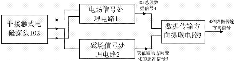
[0040] refer to figure 1 , the non-contact 485 bus online monitoring device with direction detection of the present invention includes a non-contact electromagnetic probe 102 , an electric field signal processing circuit 1 , a magnetic field signal processing circuit 2 and a data transmission direction extraction circuit 3 .

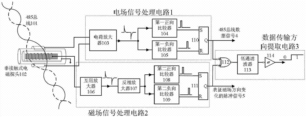
[0041] The non-contact electromagnetic probe 102 is used to simultaneously induce the electric field change signal of the two differential lines of the 485 bus and the magnetic field change signal between the two lines during the test, and output the electric field signal to the electric field signal processing circuit 1, and proceed sequentially. Through electric field signal transformation, amplification, shaping and information extraction, the data signal 4 of the 485 bus is restored; the magnetic field signal is output to the magnetic field signal processing circuit 2, and the signal transformation, amplification, shaping and information extraction of...


PUM


Abstract

The invention discloses a non-contact 485 bus on-line monitoring device having direction detection, which mainly solves the problems that the traditional detection device is easy to disturb normal working of a tested system and cannot detect data transmission direction. The non-contact 485 bus on-line monitoring device comprises a non-contact electromagnetic probe (102), an electric field signal processing circuit (1), a magnetic field signal processing circuit (2) and a data transmission direction extraction circuit (3). An electromagnetic coupling principle is utilized by the device, the electric field and magnetic field radiation signals of a 485 bus are coupled by the non-contact electromagnetic probe (102), the two signals are respectively output to the electric field processing circuit (1) and the magnetic field signal processing circuit (2) and then pass through the data transmission direction extraction circuit (3), data stream of the tested 485 bus is restored, and meanwhile, the detection function of data transmission direction is fulfilled. The non-contact 485 bus on-line monitoring device has the advantages of on-line monitoring and safety, is simple to operate, and can be used for system test and debugging and fault diagnosis.

Description

technical field [0001] The invention belongs to the technical field of circuits, and relates to a test / fault diagnosis device, which can detect the data transmission direction while monitoring the 485 bus data flow. Background technique [0002] The 485 bus is one of the most commonly used industrial standard buses, and is widely used in industrial automation, distributed measurement and control systems, building automation, mechatronics equipment, mining equipment and other fields. [0003] In the process of 485 bus system testing / fault diagnosis, the existing method is to use a third-party monitor, that is, to use a special computer or serial port recording device to monitor and record the data on the bus, and judge through the analysis of the data flow. Data error, frame format error, corresponding timeout and other faults, so as to locate the faulty device. The existing connection method of this monitoring method has the following disadvantages because it adopts a direc...

Claims


Application Information

Patent Timeline
Patent Type & Authority Patents(China)
IPC IPC(8): G05B19/418
CPCY02P90/02
Inventor 谢楷李小平刘彦明方海燕黎剑兵叶英豪
Owner XIDIAN UNIV
Why Eureka
Try Eureka