
Laser scalpel device

A scalpel and laser technology, used in surgery, parts of surgical instruments, medical science, etc., can solve problems such as uneven wound surface, and achieve the effect of overcoming uneven wound surface and eliminating matching dependence.

Inactive Publication Date: 2013-01-09
CAPITAL UNIVERSITY OF MEDICAL SCIENCES
View PDF6 Cites 7 Cited by
  • Summary
  • Abstract
  • Description
  • Claims
  • Application Information

AI Technical Summary

Problems solved by technology

[0004] The present invention provides a laser scalpel device, which is used to solve the problem of unevenness of the wound surface when the laser scalpel cuts tissue in the prior art, and eliminates the dependence of laser wavelength on the matching of tissue absorption spectrum.

Method used


Image

  • Laser scalpel device
  • Laser scalpel device
  • Laser scalpel device

Examples


Embodiment 1

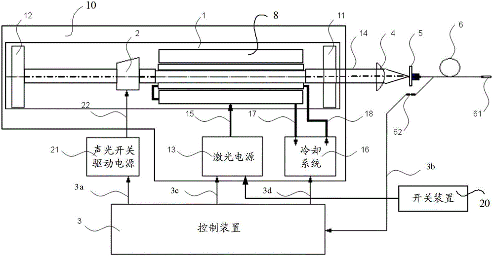
[0016] figure 1 Shown is a schematic diagram of the composition of the laser scalpel device in Embodiment 1 of the present invention. like figure 1 As shown, the laser scalpel device provided in this embodiment includes a laser light source 10, an optical fiber (referred to as "fiber") 6, a coupling mirror 4 and a knife head 61, the laser light source 10 is used to output a laser beam 14, and the coupling mirror 4 is located at The transmission optical path of the laser beam 14 is used for refracting and converging the laser beam 14 , and one end of the optical fiber 6 is located at the focal point of the coupling mirror 4 for transmitting the laser light.

[0017] The application of the laser scalpel requires a laser generating device, that is, the laser light source 10, to output a laser beam, so that the laser energy can be used to cut tissue and coagulate the wound tissue to seal the end of the blood vessel to stop bleeding.

[0018] A laser light source generally includ...

Embodiment 2

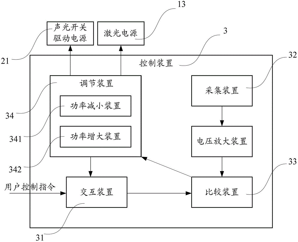
[0027] One of the key technologies for utilizing laser energy in the laser scalpel device is to control the average power of the laser light output by the laser light source 10. There are two ways to control the average power of the laser light output by the laser light source 10: one is to control the output laser light output of the laser light source 10. Duty ratio; one is to control the output laser power of the laser light source 10 when continuously outputting laser light, that is, for a laser that can be installed with an acousto-optic modulator, the laser light source can be adjusted by controlling the acousto-optic modulator to adjust the duty cycle of the output laser 10 the average power of the output laser; for the laser that can adjust the power of the laser light source 10 output laser when the laser is continuously output, such as: adjusting the working current of the laser, the current of the pump lamp, the power of the pump laser, etc., the continuous output can...


PUM


Abstract

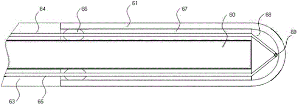
The invention provides a laser scalpel device, which comprises a laser light source, an optical fiber, a coupling mirror and a tool bit, wherein the laser light source is used for outputting laser light; the coupling mirror is positioned on a laser light transmission light path, and is used for refracting and converging the laser light; one end of the optical fiber is positioned at the focal point of the coupling mirror, and is used for transmitting laser light; the tool bit has a hollow structure; one end of the tool bit is opened, and the other end of the tool bit is enclosed; the other end of the optical fiber passes through the open port of the tool bit, and is positioned in the hollow cavity of the tool bit; and a laser light absorption medium is filled between the other end of the optical fiber and the enclosed end of the tool bit, and is used for converting absorbed laser light energy into heat energy and transmitting the heat energy to the tool bit. Due to the adoption of the laser scalpel device provided by the invention, the problem of wound surface unevenness caused by direct irradiation of laser light on cutting tissues in the prior art is solved, and the matching dependence of laser wave length on a tissue absorption spectrum is eliminated.

Description

technical field [0001] The invention relates to medical device structure technology, in particular to a laser scalpel device. Background technique [0002] The advancement of surgical operations is closely related to the invention and development of the scalpel. The blade of a traditional scalpel can cut soft tissue, and at the same time cut off the blood vessels in the tissue, causing wound bleeding. During the operation, continuous hemostasis is required, which prolongs the operation time. , It is easy to cause a series of complications after operation. How to effectively stop bleeding on the wound surface while cutting tissue is one of the difficult problems that have been studied and solved in the field of scalpel technology, and various physical means have been used to try to solve this problem. [0003] The laser scalpel in the prior art uses a mechanical light guide arm or an optical fiber to transmit laser light, irradiates tissue with laser light, and the water in ...

Claims


Application Information

Patent Timeline
Patent Type & Authority Applications(China)
IPC IPC(8): A61B18/28
Inventor 梁志远刘加峰张禄鹏
Owner CAPITAL UNIVERSITY OF MEDICAL SCIENCES
Learn More