Insulated gate bipolar translator (IGBT) ultrasonic detection tool
An ultrasonic testing and tooling technology, used in measuring devices, material analysis using sonic/ultrasonic/infrasonic waves, instruments, etc., can solve the problems of low service life of the sealing ring, reduced accuracy, inconsistent extrusion force of the sealing ring, etc. Guaranteed elasticity and times of use, preventing excessive extrusion of the sealing ring, and consistent horizontal flatness
- Summary
- Abstract
- Description
- Claims
- Application Information
AI Technical Summary
Problems solved by technology
Method used
Image
Examples
Embodiment 1
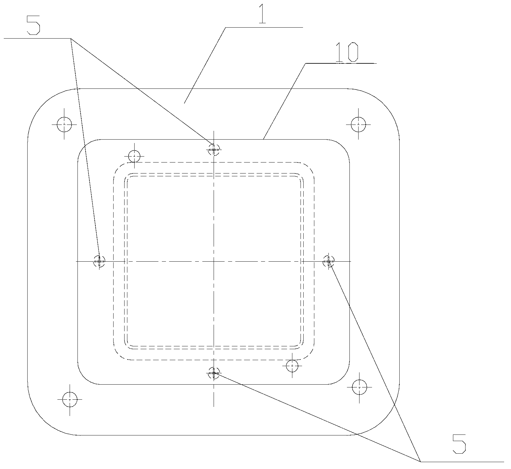
[0030] Please also see Figure 1 to Figure 4 , figure 1 It is a structural schematic diagram of the sealing mechanism of the IGBT ultrasonic testing tool disclosed in the present invention. figure 2 It is a structural schematic diagram of the IGBT ultrasonic testing tool disclosed in the present invention. image 3 It is the front view of the limit screw in the IGBT ultrasonic testing tooling disclosed by the present invention. Figure 4 It is a top view of the limit screw in the IGBT ultrasonic testing tooling disclosed by the present invention. As shown in the figure, the IGBT ultrasonic testing tooling of the present invention includes a base 1 and a sealing mechanism fixedly arranged on the base 1. The sealing mechanism includes a sealing window 2, an installation groove 3 arranged around the sealing window 2, and an installation groove located in the installation groove 3. The sealing ring 4, the outer side of the installation groove 3 is also provided with a limit me...
Embodiment 2
[0040] Such as Figure 5 As shown, the rest is the same as that of Embodiment 1, except that the limiting mechanism is three limiting rods 7 uniformly arranged outside the mounting groove 3 . By setting the limit rod, when the workpiece to be measured is evacuated and fixed, the position between the workpiece to be measured and the base is fixed, ensuring that the workpiece to be measured is effectively sealed and fixed while ensuring the service life of the sealing ring. The height setting of the rod is consistent, which can effectively ensure that the horizontal flatness of each part of the workpiece to be tested is consistent, and reduce the error during the detection of the workpiece to be measured, thereby achieving the purpose of improving the detection accuracy.
[0041] Wherein the quantity of limit rod except adopting three, also can be more than 4, 5, 6 etc. that are arranged evenly, decide according to specific needs, do not limit here.
[0042] In addition, the li...
Embodiment 3
[0044] Such as Figure 6 As shown, the rest is the same as that of Embodiment 1, the difference is that the installation groove 3 is provided with a spacer 8 that prevents the sealing ring 4 from adhering to the installation groove 3 . The contact area between the seal ring 4 and the installation groove 3 can be effectively reduced by setting the isolation part 8. When the workpiece to be measured is fixed, because the workpiece to be measured will squeeze the seal ring, the long-term extrusion effect can easily make the seal The ring 4 is bonded to the installation groove 3, so it is difficult to take it out, and it is not easy to replace the sealing ring. By setting the isolation part, the contact between the sealing ring and the installation groove is effectively reduced, which facilitates the replacement of the sealing ring later.
[0045] The isolation part 8 can be a convex point, a convex edge or a groove etc. which are evenly arranged in the installation groove 3. By a...
PUM
 Abstract
Description
Claims
Application Information
 - R&D
- Intellectual Property
- Life Sciences
- Materials
- Tech Scout
- Unparalleled Data Quality
- Higher Quality Content
- 60% Fewer Hallucinations
Browse by: Latest US Patents, China's latest patents, Technical Efficacy Thesaurus, Application Domain, Technology Topic, Popular Technical Reports.
© 2025 PatSnap. All rights reserved.Legal|Privacy policy|Modern Slavery Act Transparency Statement|Sitemap|About US| Contact US: help@patsnap.com


