
Improved pin socket for surface mount

A plug-in connector, mesh technology, applied in the field of pin sockets, can solve the problems of inaccurate function, bulky, disconnection of plug-in connectors, etc.

Active Publication Date: 2015-09-30
PREH GMBH
View PDF5 Cites 0 Cited by
  • Summary
  • Abstract
  • Description
  • Claims
  • Application Information

AI Technical Summary

Problems solved by technology

A drawback of the known design of such plug-in connectors used in surface mounting as described in European patent EP 0612204 B1 is that a force applied in a direction deviating from the actual plug-in direction during the completion of the plug-in connection can lead to plug-in connectors disconnected from the board, especially when the board has fairly bulky and / or inflexible cable assemblies connected via the plug-in connector pair, and / or the plug-in The effect of this force is not exact when the locking mechanism is connected

Method used


Image

  • Improved pin socket for surface mount
  • Improved pin socket for surface mount
  • Improved pin socket for surface mount

Examples


Embodiment Construction

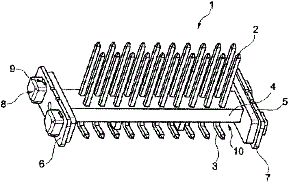
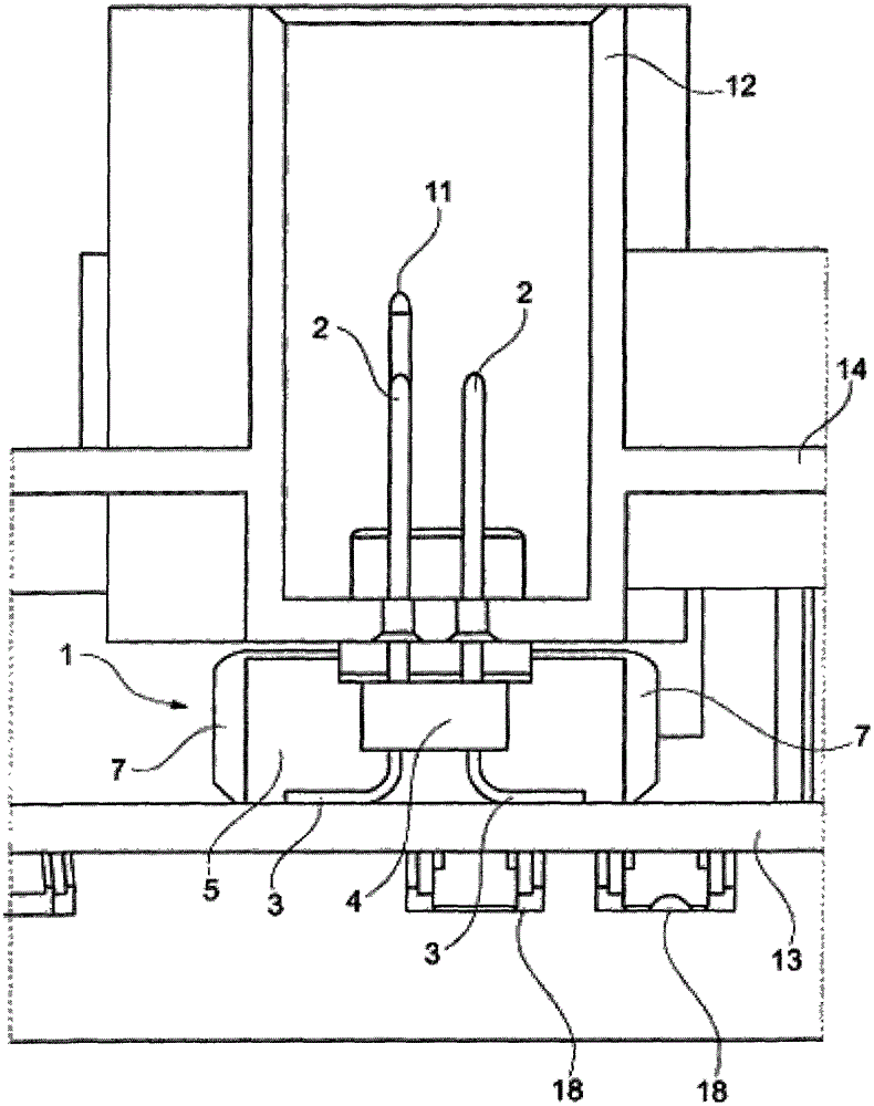
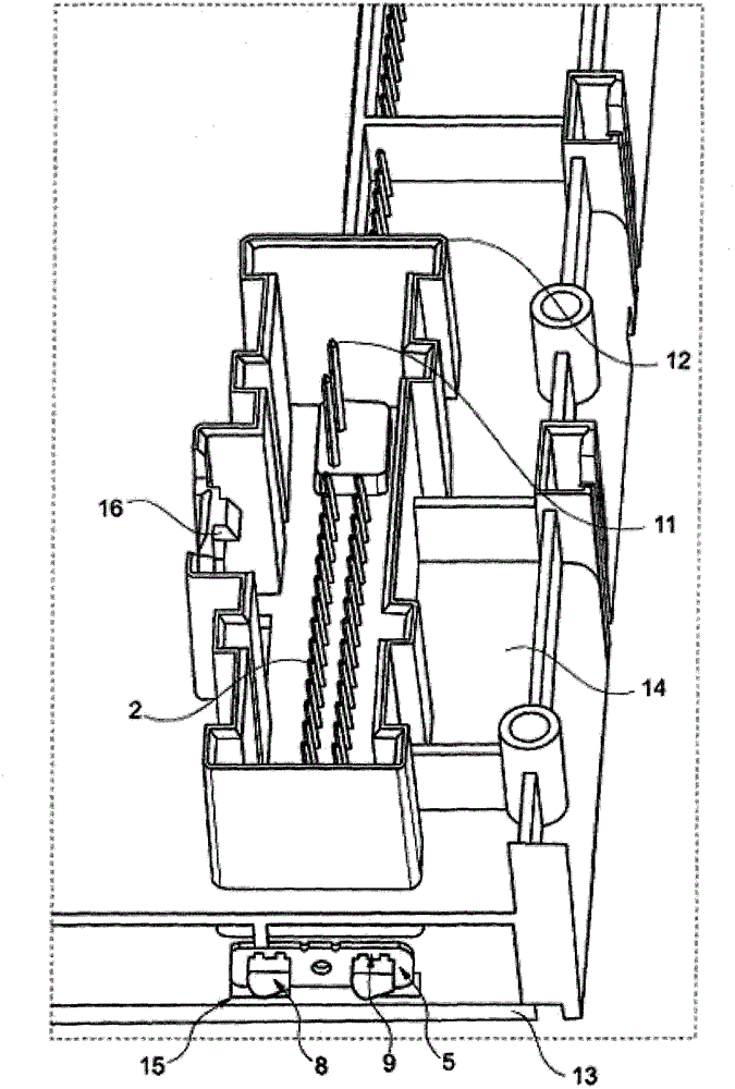
[0022] figure 1 is a specific embodiment of the present invention, wherein a pin socket is shown as the plug-in connector 1 of the present invention. The plug-in connector 1 comprises a one-piece insulating body 4 made of plastic. The insulating body 4 comprises a web-shaped central region and plates 5 on its end faces, which each extend perpendicularly to the longitudinal direction of the insulating body. A pin-shaped solderable contact 2 with a rectangular cross-section (for example made of copper) is inserted into the web-shaped intermediate region of the insulating body 4 by overmolding technology. These contacts 2 are used to establish an electrical connection with a complementary second plug-in connector (in this embodiment a card socket, which is not shown in the figure). The contacts 2 are arranged in a regular grid comprising two rows. The contact 2 includes a bent portion 3 parallel to the surface of the circuit board ( figure 1 (not shown in ), the curved portio...


PUM


Abstract

The connector e.g. pin strip (1), has a solderable contact element (2) extending through an insulating body (4), where the contact element is in direct contact with a surface of an electronic circuit board. Two solderable extension arms (5, 6) are protruded to the insulating body and engageable in direct contact with the surface of the circuit board. The extension arms are connected with the insulating body by a fitting. The contact element comprises a portion (3) that extends parallel to the surface of the circuit board, where the portion is exposed relative to the insulating body. Independent claims are also included for the following: (1) an arrangement of a circuit board and plug connector (2) a method for assembling a circuit board by a placement robot.

Description

technical field [0001] The present invention relates to a plug-in connector, such as a pin strip, used in an SMD structure (ie a so-called "Surface Mount Device" structure). Background technique [0002] Pin sockets are plug-in connectors fitted with (preferably) rows of pin terminals, used in circuit boards of electronic equipment. Its purpose is to use multiple terminals to establish a connection from one circuit board to another circuit board or to peripheral components, most commonly through a socket strip, which includes multiple spring terminals for connecting pin terminals pins to establish an electrical connection. Pin sockets often refer to male heads and card slot sockets refer to female heads. It is known to mount such plug-in connectors on circuit boards using the so-called "through-hole technology"; It is especially disadvantageous when other electronic components are used. When using surface mount, contact points are provided on the surface of the circuit b...

Claims


Application Information

Patent Timeline
Patent Type & Authority Patents(China)
IPC IPC(8): H01R13/02H01R13/46H01R13/66H01R13/73H01R12/50
CPCH01R12/57H01R12/707
Inventor M·布里J·杰格K·弗里茨
Owner PREH GMBH
Learn More