System for measuring rotation speed of aviation gasoline engine

A technology of engine speed and measurement system, which is applied to devices using electric/magnetic methods, etc., can solve the problems of inaccurate measurement of probes, affecting the dynamic balance of rotating parts, and inability to embed magnetic materials, and achieves simple speed measurement principle and speed range. wide effect

Active Publication Date: 2012-12-26
SHENYANG INST OF AUTOMATION - CHINESE ACAD OF SCI
View PDF6 Cites 2 Cited by
  • Summary
  • Abstract
  • Description
  • Claims
  • Application Information

AI Technical Summary

Problems solved by technology

The embedded magnetic beads affect the dynamic balance of the rotating parts. At the same time, because the distance between the embedded magnetic beads on the rotating plane and the distance between the Hall sensor cannot be kept constant, the magnetic signal strength may be insufficient during the measurement process, resulting in inaccurate measurements or failure to complete the measurement normally.
In addition, some special parts cannot be embedded in magnetic materials
The photoelectric encoder needs to be installed on the output shaft of the engine, the installation workload is heavy, and the measuring device is easily damaged at high speed
In addition, the sensor of the photoelectric encoder is easily polluted by dust in the atmosphere, lubricating oil of the engine, etc., causing the probe to be blocked and resulting in inaccurate measurement
Its working reliability is not high in harsh environments, and it is easily affected by sunlight outdoors

Method used


Image

  • System for measuring rotation speed of aviation gasoline engine
  • System for measuring rotation speed of aviation gasoline engine

Examples


Embodiment Construction

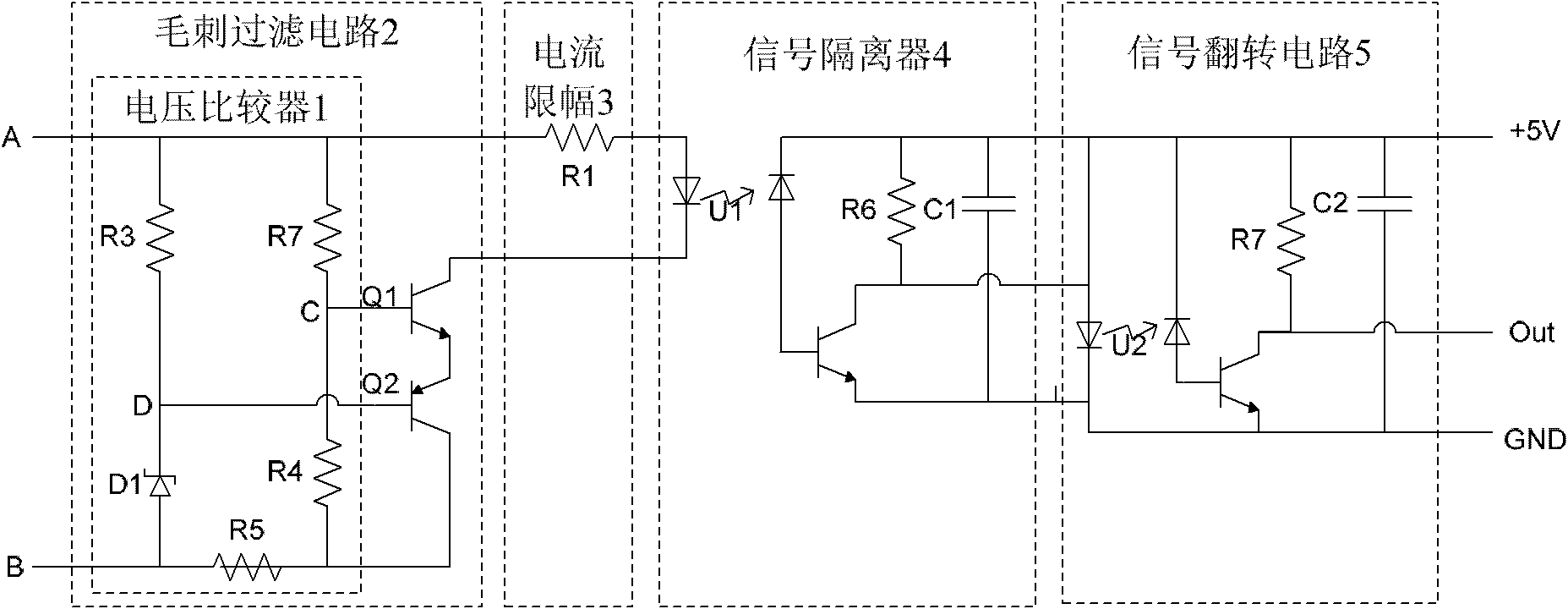
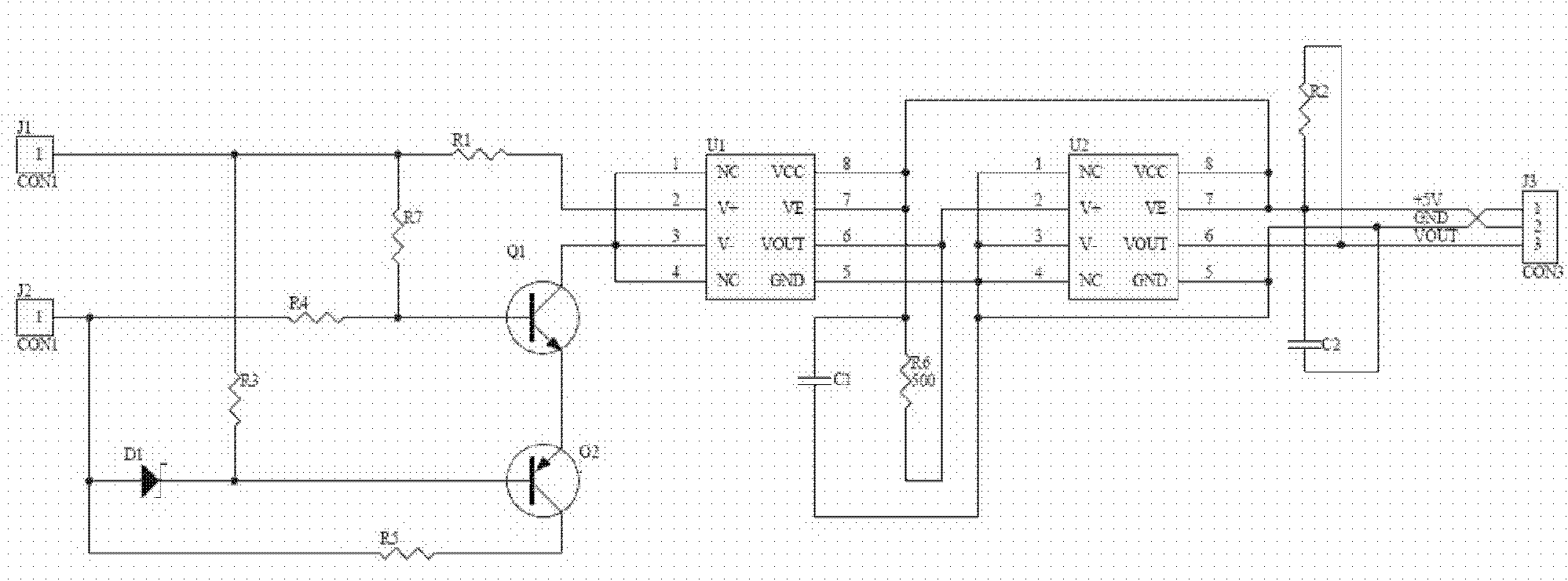
[0017] An aviation gasoline engine speed measurement system, such as figure 1 , 2 shown. Taking the ignition generator of the engine as the signal source, the system includes a glitch filter unit 2 , a current limiting unit 3 , a signal isolation unit 4 and a signal inversion unit 5 .

[0018] The input end of the glitch filtering unit 2 is connected with the ignition generator of the generator, and the output end of the glitch filtering unit 2 is connected with the current limiting unit 3; the input end of the current limiting unit 3 is connected with the glitch filtering unit 2, and the current The output terminal of the limiting unit 3 is connected to the signal isolation unit 4; the input terminal of the signal isolation unit 4 is connected to the current limiting unit 3, and the output terminal of the signal isolation unit 4 is connected to the signal inversion unit 5; the input terminal of the signal inversion unit 5 It is connected with the signal isolation unit 4, an...


PUM


Abstract

The invention discloses a system for measuring the rotation speed of an aviation gasoline engine. An ignition generator of the engine is used as a signal source; the system comprises a burr filtering unit, a current amplitude limiting unit, a signal isolating unit and a signal turnover unit, wherein the input end of the burr filtering unit is connected with the ignition generator of the engine; the output end of the burr filtering unit is connected with the current amplitude limiting unit; the input end of the current amplitude limiting unit is connected with the burr filtering unit; the output end of the current amplitude limiting unit is connected with the signal isolating unit; the input end of the signal isolating unit is connected with the current amplitude limiting unit; the output end of the signal isolating unit is connected with the signal turnover unit; the input end of the signal turnover unit is connected with the signal isolating unit; and the output end of the signal turnover unit is connected with an engine rotation speed controller. According to the system, sensitive devices need not to be installed on an engine rotation component, and the rotation speed of the engine is calculated through ignition pulses of the ignition generator of the engine; the speed measurement is not influenced by the lighting, a strong magnetic field and a strong electric field; and the system is simple in principle and is reliable.

Description

technical field [0001] The invention relates to the technical field of engine electronic control, in particular to an aviation gasoline engine rotation speed measurement system. Background technique [0002] The small aviation gasoline engine used by drones is light in weight and simple in structure. When in use, the operator needs to monitor the rotational speed of the engine or control the rotational speed of the engine within a certain range. It is necessary to measure the speed of the engine directly or indirectly. Traditional engine speed measurement often needs to embed magnetic beads on the rotating parts, or realize it by connecting an external photoelectric encoder on the rotating shaft. The embedded magnetic beads affect the dynamic balance of the rotating parts. At the same time, because the distance between the embedded magnetic beads on the rotating plane and the distance between the Hall sensor cannot be kept constant, the magnetic signal strength may be insu...

Claims


Application Information

Patent Timeline
Patent Type & Authority Applications(China)
IPC IPC(8): G01P3/46
Inventor 韩建达戴磊齐俊桐吴镇炜吴冲
Owner SHENYANG INST OF AUTOMATION - CHINESE ACAD OF SCI
Why Eureka
Try Eureka