Slidable main unit base of continuous drilling fluid circulating system

A circulation system and drilling fluid technology, applied in the field of petroleum drilling machinery, can solve the problem that the main engine cannot move laterally

Inactive Publication Date: 2012-12-19
BC P INC CHINA NAT PETROLEUM CORP +1
View PDF5 Cites 0 Cited by
  • Summary
  • Abstract
  • Description
  • Claims
  • Application Information

AI Technical Summary

Problems solved by technology

[0003] In order to solve the problem that the main engine of the existing drilling fluid continuous circulation system cannot move laterally

Method used


Image

  • Slidable main unit base of continuous drilling fluid circulating system

Examples


Embodiment Construction

[0009] The present invention will be further described below in conjunction with accompanying drawing:

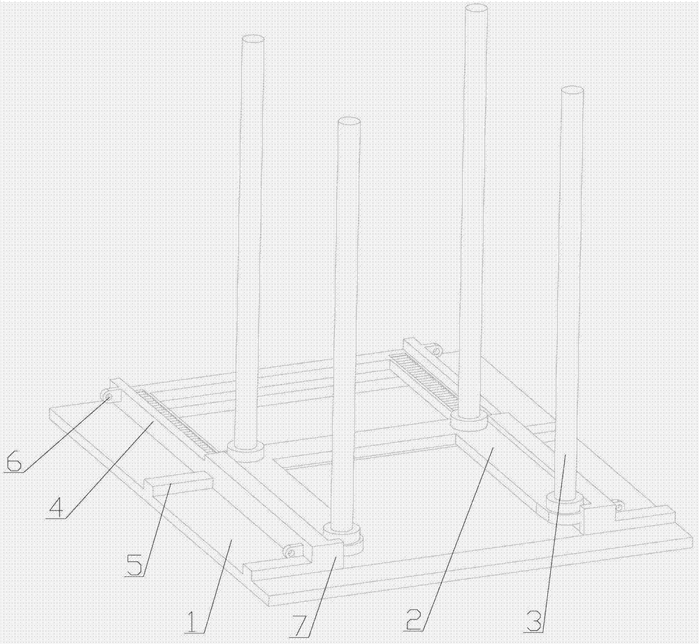
[0010] As shown in the accompanying drawings, the slidable base of the main engine of the drilling fluid continuous circulation system includes a base 1 , a carriage 2 and a hydraulic piston rod 3 . Both sides of the base 1 are fixed with sideways channel-shaped slideways 4, through which the slide frame 2 can move laterally. The top of the rear half of the slideway 4 is open, which is convenient for loading and unloading the slide frame 2. The bottom surface of the slideway 4 is a needle-type sliding surface, which reduces the frictional resistance of the carriage 2 . The front end of the slideway 4 is fixedly connected with a limiting plate 7 to limit the sliding frame 2 from sliding out of the slideway 4 . The carriage 2 is a U-shaped plate, the protruding parts on both sides of the carriage 2 are slidably connected in the slideway 4, the hydraulic piston rod 3 is vert...


PUM


Abstract

A slidable main unit base of a continuous drilling fluid circulating system mainly solves the problem that an existing main unit of a continuous drilling fluid circulating system cannot move transversely. The slidable main unit base is characterized in that lateral slide rails (4) in the shape of inverted steel channels are fixed to two sides of a base (1), the upper surface of the rear half portion of each slide rail (4) is open, the bottom surface of each slide rail (4) is a rolling needle type sliding surface, a fixing plate (7) is fixedly connected to the front end of each slide rail (4), a slide carrier (2) is a U-shaped plate, protruded portions on two sides of the slide carrier (2) are slidably connected into the slide rails (4), and hydraulic piston rods (3) are perpendicularly fixed onto four corners of the slide carrier (2). The slidable main unit base of the continuous drilling fluid circulating system has the advantage of capability of moving transversely.

Description

technical field [0001] The invention relates to a petroleum drilling machine, in particular to a slidable main engine base of a drilling fluid continuous circulation system. Background technique [0002] The existing drilling fluid continuous circulation system. The base of the main engine is placed on the drilling floor, and the main engine of the continuous circulation system is connected to the base of the main engine through four hydraulic piston rods. The main engine can use hydraulic power to move up and down, but the main engine cannot move laterally, resulting in a series of problems: a main engine seal The system cannot seal the outer annular space of the drill collar, and the slips of the main engine itself cannot be used as the slips of the drill collar. When pulling out to the drill collar, not only cannot realize the continuous circulation of drilling fluid, but also hinder the pull-out operation of the drill collar; When implementing underbalanced drilling ope...

Claims


Application Information

Patent Timeline
Patent Type & Authority Applications(China)
IPC IPC(8): E21B21/00
Inventor 窦金永于成龙谢从辉
Owner BC P INC CHINA NAT PETROLEUM CORP
Why Eureka
Try Eureka